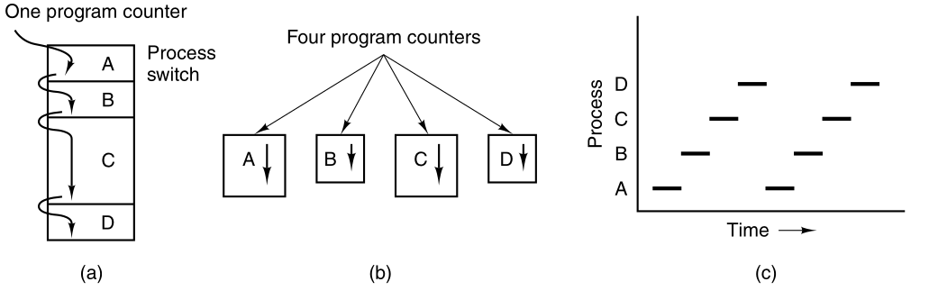
(a) We see a computer multiprogramming four programs in memory.
The most central concept in any operating system is the
process:
an abstraction of a running program.
Everything else hinges on this concept.
Multi-tasking
All modern computers can do several things at the same time.
While running a user program,
a computer can also be reading from a disk,
and outputting text to a screen, etc.
The CPU also switches from program to program,
running each for tens or hundreds of milliseconds.
Pseudo-parallelism
While, strictly speaking, at any instant of time,
the CPU is running only one program,
in the course of 1 second, it may work on several programs,
thus giving the users the illusion of parallelism.
Sometimes people speak of pseudo-parallelism in this context,
to contrast it with the true hardware parallelism of multiprocessor
systems
(which have two or more CPUs sharing the same physical memory).
Keeping track of multiple, parallel activities is hard for people to
do.
Operating system designers designed an evolving conceptual model,
(sequential processes) that makes parallelism easier to deal with.
All the runnable software on the computer,
sometimes including the operating system,
is organized into a number of sequential processes.
A process is just an executing program, including:
current values of the program counter register, other registers, and
variables.
https://en.wikipedia.org/wiki/Computer_multitasking
Conceptually, each process has its own virtual CPU.
The real CPU switches back and forth from process to process.
It is much easier to think about a collection of processes running in
(pseudo) parallel,
than to try to keep track of how the CPU switches from program to
program.
This rapid switching back and forth is called multiprogramming.
(a) We see a computer multiprogramming four programs in memory.
Conceptual model of four independent, sequential processes.
We see four processes, each with its own flow of control
(i.e., its own program counter register),
and each one running independently of the other ones.
Of course, there is only one physical program counter register,
so when each process runs,
its logical program counter is loaded into the real program counter
register.
When it is finished for the time being,
the physical program counter register is saved in the process’ logical
program counter in memory.
Only one program is active at any instant.
We see that viewed over a long enough time interval,
all the processes have made progress,
but at any given instant only one process is actually running.
With the CPU switching back and forth among the processes,
the rate at which a process performs its computation will not be
uniform,
and probably not even reproducible, if the same processes are run
again.
Processes must not be programmed with built-in assumptions about
timing.
Consider an I/O process that starts a tape to restore backed up
files,
executes an idle loop 10,000 times to let it get up to speed,
and then issues a command to read the first record.
If the CPU decides to switch to another process during the idle
loop,
then the tape process might not run again,
until after the first record was already past the read head.
When a process has critical real-time requirements,
that is, particular events must occur within a specified number of
milliseconds,
special measures must be taken to ensure that they do occur.
Normally, however, most processes are not affected by the underlying
multiprogramming of the CPU,
or the relative speeds of different processes.
The difference between a process and a program is subtle, but
crucial.
A process is an activity of some kind.
It has a program, input, output, and a state.
A single processor may be shared among several processes,
with some scheduling algorithm being used,
to determine when to stop work on one process and service a different
one.
Operating systems need some way to make sure all the necessary processes exist.
Simple embedded systems
In very simple systems, or in systems designed for running only a single
application
(e.g., controlling a device in real time),
it may be possible to have all the processes that will ever be
needed,
be present when the system comes up.
General purpose systems
Some way is needed to create and terminate processes,
as needed during operation.
There are four principal events that cause processes to be
created:
1) System initialization.
2) Execution of a process creation system call by a running
process.
3) A user request to create a new process.
4) Initiation of a batch job.
When an operating system is booted,
often several processes are created.
Some of these are foreground processes, that is,
processes that interact with (human) users and perform work for
them.
Others are background processes,
which are not associated with particular users,
but instead have some specific function.
For example, web server:
A background process may be designed to accept incoming requests,
for web pages hosted on that machine,
waking up when a request arrives to service the request.
Processes that stay in the background to handle some activity,
such as web pages, printing, and so on are called daemons.
Large systems commonly have dozens of them.
In MINIX3, the ps program can be used to list the running
processes:
ps
In addition to the processes created at boot time,
new processes can be created afterward as well.
Often a running process will issue system calls,
to create one or more new processes to help it do its job.
Creating new processes is particularly useful under the condition
that,
the work to be done can easily be formulated in terms of several
related,
but otherwise independent, interacting processes.
Compiler example
For example, when compiling a large program,
the make program invokes the C compiler,
to convert source files to object code,
and then it invokes the install program,
to copy the program to its destination,
set ownership and permissions, etc.
In MINIX3, the C compiler itself is actually several different programs,
which work together.
These include a pre-processor, a C language parser,
an assembly language code generator, an assembler, and a linker.
In interactive systems, users can start a program by typing a
command.
Virtual consoles allow a user to start a program,
say a compiler, and then switch to an alternate console, and start
another program,
perhaps to edit documentation while the compiler is running.
MINIX3 supports four virtual terminals.
You can switch between them using ALT+F1 through
ALT+F4.
The last situation in which processes are created,
applies only to the batch systems found on large mainframes /
HPCs.
Here users can submit batch jobs to the system (possibly
remotely).
When the operating system decides that it has the resources to run
another job,
it creates a new process, and in it, runs the next job from the input
queue.
Technically, in all these cases, a new process is created,
by having an existing process execute a process creation system
call.
That process may be:
a running user process,
a system process invoked from the keyboard or mouse, or
a batch manager process.
What that process does is execute a system call to create the new
process.
This system call tells the operating system to create a new
process,
and indicates, directly or indirectly, which program to run in it.
In MINIX3, there is only one system call to create a new
process:
fork
This call creates an exact clone of the calling process.
After the fork, the two processes, the parent and the child,
have the same memory image, the same environment strings, and the same
open files.
That is all there is.
Usually, the child process then executes execve or a
similar system call,
to change its memory image and run a new program.
For example, when a user types a command to the shell, for
example:
sort
the shell forks off a child process,
and the child executes sort.
Why fork, then execute?
The two-step process allows the child to:
manipulate its file descriptors after the fork, but before the
execve,
to accomplish redirection of standard input, standard output, and
standard error.
Memory is mostly separate between parent and child
processes.
In both MINIX3 and UNIX, after a process is created,
both the parent and child have their own distinct address spaces.
If either process changes a word in its address space,
the change is not visible to the other process.
The child’s initial address space is a copy of the parent’s,
but there are two distinct address spaces involved;
no writable memory is shared
Like some UNIX implementations,
MINIX3 can share the program text between the two,
since that cannot be modified.
A newly created process can share some of its creator’s other resources,
such as open files.
After a process has been created,
it starts running and does whatever its job is.
A process usually terminates due to one of the following
conditions:
1) Normal exit (voluntary).
2) Error exit (voluntary).
3) Fatal error (involuntary).
4) Killed by another process (involuntary).
Most processes terminate because they have done their work.
When a compiler has compiled the program given to it,
the compiler executes a system call to tell the operating system that it
is finished.
This system call is exit in MINIX3.
Screen-oriented programs also support voluntary termination.
For example, editors have a key combination the user can invoke,
to tell the process to save the working file,
remove any temporary files that are open, and terminate.
An error caused by the process, perhaps due to a program bug.
Examples include:
executing an illegal instruction, referencing nonexistent memory, or
dividing by zero.
In MINIX3, a process can tell the operating system that it wishes to
handle certain errors itself,
in which case the process is signaled (interrupted) instead of
terminated,
when one of the errors occurs.
A process discovers a fatal error.
For example, if a user types the command:
cc foo.c
to compile the program foo.c and no such file exists,
the compiler simply exits.
One process can execute a system call telling the OS to kill another
process.
In MINIX3, this call is:
kill
Of course, the killer must have the necessary authorization to kill the
killee.
Inherited death?
In some systems, when a process terminates, either voluntarily or
otherwise,
all processes it created are immediately killed as well.
MINIX3 does not work this way, however.
In some systems, when a process creates another process,
the parent and child continue to be associated in certain ways.
The child can itself create more processes, forming a process
hierarchy.
A process has only one parent (but zero, one, two, or more
children).
Signaling process groups:
In MINIX3, a process, its children, and further descendants,
together may form a process group.
When a user sends a signal from the keyboard,
the signal may be delivered to all members of the process group,
currently associated with the keyboard
(usually all processes that were created in the current window).
This is signal-dependent.
If a signal is sent to a group, each process can:
catch the signal,
ignore the signal, or
take the default action (to be killed by the signal).
As a simple example of how process trees are used,
let us look at how MINIX3 initializes itself.
Two special programs, the reincarnation server, and
init, are present in the boot image.
Reincarnation server
The reincarnation server’s job is to (re)start drivers and
servers.
It begins by blocking, waiting for a message telling it what to
create.
Init
In contrast, init executes the /etc/rc
script,
that causes it to issue commands to the reincarnation server,
to start the drivers and servers not present in the boot image.
Next, init manages all the terminals.
It reads a configuration file /etc/ttytab,
to see which terminals and virtual terminals exist.
init forks a getty process for each one,
displays a login prompt on it,
and then waits for input.
For each terminal,
when a username is typed,
getty execs a login process with the username as its
argument.
If the user succeeds in logging in,
then login will exec the user’s shell.
So the shell is a child of init.
User commands create children of the shell,
which are grandchildren of init.
Parent-driven init enables restarting failed
processes:
This procedure makes sure the drivers and servers are started as
children of the reincarnation server,
so if any of them ever terminate,
the reincarnation server will be informed and can restart (i.e.,
reincarnate) them again.
This allows MINIX3 to tolerate a driver or server crash,
because a new one will be started automatically.
+++++++++++++++++ Cahoot-02-1
Each process has it’s own data, including:
program counter register, general purpose registers, stack, open files,
alarms, and other internal state,
Data needs to be moved between processes.
Processes often need to interact, communicate, and synchronize with
other processes.
One process may generate some output,
that another process should use as input.
Example: grep may be ready before cat is done.
In the shell command
cat chapter1 chapter2 chapter3 | grep tree
the first process, running cat, concatenates and outputs
three files.
The second process, running grep,
selects all lines containing the word tree.
Depending on the relative speeds of the two processes
(which depends on both the relative complexity of the programs,
and how much CPU time each one has had),
it may happen that grep is ready to run,
but there is no input waiting for it.
It must then block until some input is available.
When a process blocks, it does so because logically it cannot
continue,
typically because it is waiting for input that is not yet available.
It is also possible for a process that is conceptually ready and able
to run,
to be stopped because the operating system has decided to allocate the
CPU to another process for a while.
These two conditions are completely different.
In the first case, the waiting (blocking) is inherent in the
problem
(you cannot process the user’s command line until it has been
typed).
In the second case, it is a technicality of the scheduling
system.
There are not enough CPUs to give each process its own private
processor.
Processes transition between three states:
1) Running (actually using the CPU at that instant).
2) Ready (runnable; temporarily stopped to let another process
run).
3) Blocked (unable to run until some external event happens).
Running versus ready:
The first two states are similar.
In both running and ready states, the process is willing to run.
In ready, there is temporarily no CPU available for it.
Blocked:
The blocked state is different from the first two.
The process cannot run because it is waiting on something,
even if the CPU has nothing else to do.
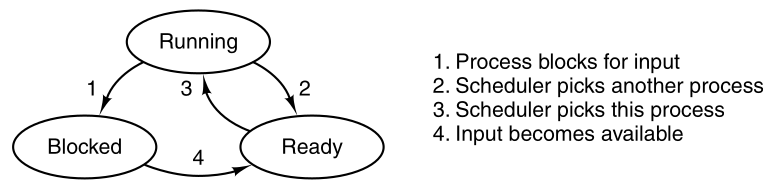
A process can be in running, blocked, or ready state.
Transitions between these states are as shown.
Four transitions are possible among these three states, as shown.
A running process discovers that it cannot continue.
In MINIX3,
when a process reads from a pipe or special file
(e.g., a terminal) and there is no input available,
the process is automatically moved from the running state to the blocked
state.
In some systems, a process must execute a system call,
block or pause to get into blocked state.
are caused by the process scheduler,
a part of the operating system,
without the process even knowing about them.
Transition 2: Running to ready
occurs when the scheduler decides that the running process has run long
enough,
and it is time to let another process have some CPU time.
Transition 3: Ready to running
occurs when all the other processes have had their fair share,
and it is time for the first process to get the CPU to run again.
Scheduling
decide which process should run when and for how long.
Many algorithms have been devised,
to try to balance the competing demands of efficiency for the system as
a whole,
and fairness to individual processes.
occurs when the external event for which a process was waiting
(e.g., the arrival of some input) happens.
If no other process is running then,
transition 3 will be triggered immediately,
and the process will start running.
Otherwise it may have to wait in ready state for a little while,
until the CPU is available.
Some of the processes run programs that carry out commands typed in
by a user.
Other processes are part of the system,
and handle tasks such as carrying out requests for file services,
or managing the details of running a disk or a tape drive.
Example: disk access
When a disk interrupt occurs,
the system may make a decision to stop running the current
process,
and run the disk process,
which was blocked waiting for that interrupt.
We say “may” because it depends upon relative priorities,
of the running process and the disk driver process.
Instead of thinking about interrupts,
we can think about user processes, disk processes, terminal processes,
and so on,
which block when they are waiting for something to happen.
When the disk block has been read, or the character typed,
the process waiting for it is unblocked,
and is eligible to run again.
The scheduler is at the lowest level of abstraction of the OS,
with a variety of abstracted processes on top of it.
All the interrupt handling, and details of actually starting and
stopping processes,
are hidden away in the scheduler, which is actually quite small.
The rest of the operating system is nicely structured in process
form.
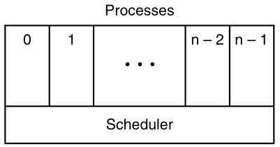
The lowest layer of a process-structured operating system handles
interrupts and scheduling.
Above that layer, sequential processes exist.
The “scheduler” is not the only thing in the lowest abstraction
layer,
there is also support for interrupt handling and inter-process
communication.
++++++++++++ Cahoot-02-2
When the process is switched from running to ready state,
it can be restarted later, as if it had never been stopped.
However, it’s resources are stored in central locations (registers,
etc.).
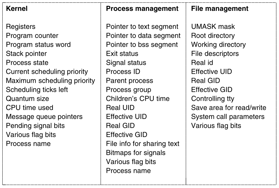
To implement the process,
the operating system maintains a process table,
with one entry per process.
Some authors call these entries process control blocks.
Each entry in the table includes everything about the process that
must be saved, including:
its program counter registers, general purpose registers, stack pointer,
memory allocation, the status of its open files, its accounting and
scheduling information, alarms, and other signals.
In MINIX3, inter-process communication, memory management, and file
management,
are each handled by separate modules within the system,
so the process table is partitioned,
with each module maintaining the fields that it needs.
The image below shows some important fields in the process
table.
The fields in the first column are the only ones relevant to this
section.
The 2nd two columns illustrate information is needed elsewhere in the
system:
Demonstrate:
Show the actual process table in running Minix3.
The illusion of multiple sequential processes is maintained,
on a machine with one CPU and many I/O devices.
Now we describe the “scheduler” works in MINIX3,
but most modern operating systems work essentially the same way.
Associated with each I/O device class
(e.g., floppy disks, hard disks, timers, terminals)
is a data structure in a table called the interrupt descriptor
table.
The most important part of each entry in this table is called the
interrupt vector.
It contains the address of the interrupt service procedure.
A user process transitions from running to
ready:
Suppose that a “user process” is in running state.
Another process, a “disk process” needs to access a disk.
Thus, a disk interrupt occurs from a “disk process”,
which is now in blocked state.
Interrupt hardware pushes registers to stack:
The program counter, program status word, and possibly one or more
registers,
are all pushed onto the (current) stack by the interrupt hardware.
On the stack, they may now be used by the interrupt service
procedure.
Interrupt service procedure stores “user process”
data:
The computer then jumps to the address specified in the disk interrupt
vector.
The interrupt service procedure saves all the registers,
in the process table entry for the current process.
The current process number and a pointer to its entry are kept,
in global variables so they can be found quickly.
Actions such as saving the registers and setting the stack
pointer,
cannot even be expressed in high-level languages such as C,
so those action are taken by a small assembly language routine.
Interrupt service procedure clears space for “disk
process”:
Then, the information deposited by the interrupt is removed from the
stack,
and the stack pointer is set to a temporary stack used by the process
handler.
Perform interrupt job:
When this data transition routine is finished,
it calls a C procedure to do the rest of the actual work,
for this specific interrupt type.
Message the “disk process” that interrupted the
CPU:
inter-process communication in MINIX3 is via messages.
The disk process is blocked waiting for a message.
Thus, the next step is to build a message to be sent to the disk
process.
The message says that an interrupt occurred,
to distinguish it from messages from user processes,
requesting disk blocks to be read, and things like that.
“Disk process” is now in ready state:
The state of the disk process is now changed from blocked to
ready,
and the scheduler is called.
In MINIX3, different processes have different priorities,
to give better service to I/O device handlers than to user processes,
for example.
Schedule “user process” or “disk process:
If the disk process is now the highest priority runnable process,
it will be scheduled to run.
If the process that was interrupted is just as important, or more
so,
then it will be scheduled to run again,
and the disk process will have to wait a little while.
Data for current process copied back to central
storage:
Either way, the C procedure called by the assembly language interrupt
code now returns,
and the assembly language code loads up both the registers and memory
map,
for the now-current process, and starts it running.
Interrupt handling and scheduling are summarized in the image
below.
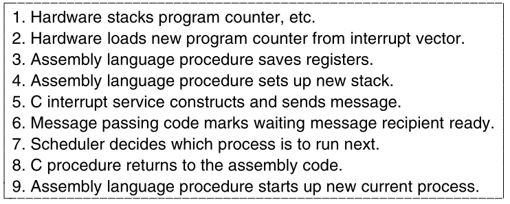
This is what lowest level of the operating system does when an interrupt
occurs.
The details may vary slightly from system to system.
In traditional operating systems,
each process has an address space, and a single thread of control.
In fact, that is almost the definition of a process.
Sometimes we have multiple threads of control in the same address
space,
running in quasi-parallel,
as though they were separate processes
(except for the shared address space).
These threads of control are usually just called threads,
although some people call them lightweight processes.
A process can group related resources together.
A process has an address space containing:
program text, data, and other resources.
These resources may include open files, child processes,
pending alarms, signal handlers, accounting information, and more.
The other concept a process has is a thread of execution,
usually shortened to just thread.
Threads have their own register data and
stack:
The thread has a program counter register,
that keeps track of which instruction to execute next.
It is also known as the Instruction Pointer Register (RIP) (on
x86).
It also has other registers, which hold its current working
variables.
It has a stack, which contains the execution history,
with one frame for each procedure called but not yet returned from.
Although a thread must execute in some process,
the thread and its process are different concepts,
and can be treated separately.
Processes are used to group resources together.
Threads are the entities scheduled for execution on the CPU.
What threads add to the process model,
is to allow multiple executions to take place in the same process
environment,
to a large degree independent of one another.
This makes sharing data between threads easier and more efficient.
Traditional process versus multi-thread process:
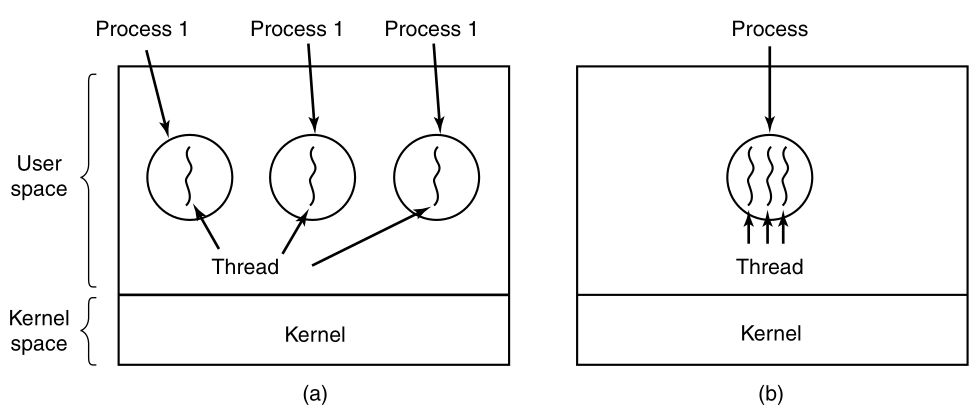
(a) Three traditional processes each with one thread.
Each process has its own address space, and a single thread of
control.
(b) One single process, with three threads of control.
Although in both cases we have three threads,
in (a) each of them operates in a different address space,
whereas in (b) all three of them share the same address space.
In (b) the stacks will be sequentially organized in that address
space.
As an example of where multiple threads might be used,
consider a web browser process.
Many web pages contain multiple small images.
For each image on a web page,
the browser must set up a separate connection to the page’s home
site,
and request the image.
A great deal of time is spent establishing and releasing all these
connections.
By having multiple threads within the browser,
many images can be requested at the same time,
speeding up performance in most cases since with small images,
the set-up time is the limiting factor,
not the speed of the transmission line.
When multiple threads are present in the same address space,
a few of the fields of the process table we showed above,
are not actually per process,
but per thread, so a separate thread table is needed,
with one entry per thread.
Per-thread data:
Among the per-thread items are the:
program counter register (e.g., RIP), registers, and state.
The program counter is needed because threads,
like processes, can be suspended and resumed.
The registers are needed,
because when threads are suspended,
their registers must be saved.
Thread states:
Finally, threads, like processes, can be in:
running, ready, or blocked state.
The image below lists some per-process and per-thread items:
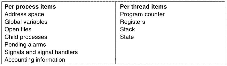
The first column lists some items shared by all threads in a
process.
The second one lists some items private to each thread.
+++++++++++++++++++ Cahoot-02-3
The OS can be in kernel or user space.
In some systems, the kernel is not aware of the threads.
They are managed entirely in user space.
When a thread is about to block,
it chooses and starts its successor, before stopping.
Several user-level threads packages were in common use,
including the POSIX P-threads and Mach C-threads packages.
Some kernels are aware of multiple threads per process,
so when a thread blocks, the kernel chooses the next one to run,
either from the same process or a different one.
To do scheduling, the kernel must have a thread table,
that lists all the threads in the system,
analogous to the process table.
Although these two alternatives may seem equivalent,
they differ considerably in performance.
Switching threads is much faster when thread management is done in
user space,
rather than when a system call is needed.
This fact argues strongly for doing thread management in user space.
On the other hand, when threads are managed entirely in user
space,
and one thread blocks
(e.g., waiting for I/O, or a page fault to be handled),
then the kernel blocks the entire process,
since it is not even aware that other threads exist.
This fact as well as others argue for doing thread management in the
kernel.
As a consequence, both systems are in use,
and various hybrid schemes have been proposed as well.
Whether threads are managed by the kernel or in user space,
they introduce problems that must be solved,
and which change the programming model appreciably.
Consider the effects of the fork system call.
If the parent process has multiple threads,
should the child also have them?
If not, the process may not function properly,
since all of them may be essential.
However, if the child process gets as many threads as the parent,
what happens if a thread was blocked on a read call,
for example, from the keyboard?
Are two threads now blocked on the keyboard?
When a line is typed, do both threads get a copy of it?
Only the parent?
Only the child?
The same problem exists with open network connections.
Another class of problems is related to the fact that:
threads share many data structures.
What happens if one thread closes a file,
while another one is still reading from it?
Suppose that one thread notices that there is too little
memory,
and starts allocating more memory.
Then, part way through, a thread switch occurs,
and the new thread also notices that there is too little memory,
and also starts allocating more memory.
Does the allocation happen once or twice?
In nearly all operating systems that were not designed with threads in
mind,
the libraries (such as the memory allocation procedure) are not
re-entrant,
and will crash if a second call is made while the first one is still
active.
https://en.wikipedia.org/wiki/Reentrancy_(computing)
A subroutine is called re-entrant,
if multiple invocations can safely run concurrently on multiple
processors,
or if on a single-processor system its execution can be
interrupted,
and a new execution of it can be safely started (it can be
“re-entered”).
Another problem relates to error reporting.
In UNIX, after a system call,
the status of the call is put into a global variable,
errno.
What happens if a thread makes a system call,
and before it is able to read errno,
another thread makes a system call,
wiping out the original value?
Some signals are logically thread specific; others are not.
For example, if a thread calls alarm,
it makes sense for the resulting response signal to go to the thread
that made the call.
When the kernel is aware of threads,
it can usually make sure the right thread gets the signal.
When the kernel is not aware of threads,
the threads package must keep track of alarms by itself.
An additional complication for user-level threads exists when (as in
UNIX),
a process may only have one alarm at a time pending,
and several threads call alarm independently.
Other signals, such as a keyboard-initiated SIGINT,
are not thread specific.
Who should catch them?
One designated thread?
All the threads?
A newly created thread?
Each of these solutions has problems.
What happens if one thread changes the signal handlers,
without telling other threads?
One last problem introduced by threads is stack management.
In many systems, when stack overflow occurs,
the kernel just provides more stack, automatically.
When a process has multiple threads,
it must also have multiple stacks.
If the kernel is not aware of all these stacks,
it cannot grow them automatically upon stack fault.
In fact, it may not even realize that a memory fault is related to stack
growth.
These problems are certainly not insurmountable.
However, just introducing threads into an existing system,
without a substantial system redesign, does not work.
The semantics of system calls have to be redefined,
and libraries have to be rewritten, at the very least.
And all of these modifications must be backward compatible with existing
programs,
for the limiting case of a process with only one thread.
Processes frequently need to communicate with other processes.
For example, in a shell pipeline,
the output of the first process must be passed to the second
process,
Further, pipelines can be chained.
There is a need for communication between processes,
preferably in a well-structured way, not using interrupts.
There are three issues here:
First,
How can one process pass information to another?
Second,
How can two or more processes not get into each other’s way,
when engaging in “critical” activities on shared resources?
For example, what if two processes each try to grab the last 1 MB of
memory?
Third,
When order dependencies are present,
how can the OS maintain proper sequencing?
If process A produces data, and process B prints it,
then B has to wait until A has produced some data,
before starting to print.
We will examine all three of these issues.
IPC for threads?
It is also important to mention that two of these issues apply equally
well to threads.
The first one, passing information, is easy for threads,
since they share a common address space.
Threads in different address spaces, that need to communicate,
fall under the category of communicating processes.
However, the other two,
keeping out of each other’s hair,
and proper order sequencing,
apply as well to threads.
The same problems exist and the same solutions apply.
Below we will discuss the problem in the context of processes,
but the same problems and solutions also apply to threads.
https://en.wikipedia.org/wiki/Race_condition
Processes that are working together may share some common
resource,
that each one can read and write.
The shared storage may be in main memory (possibly in a kernel data
structure)
or it may be a shared file on disk.
The location of the shared memory does not change the nature of the
communication,
or the problems that arise.
To see how inter-process communication works in practice,
let us consider a simple but common example, a print spooler.
When a process wants to print a file,
it enters the file name in a special spooler directory.
Another process, the printer daemon,
periodically checks to see if there are any files to be printed,
and if so, removes their names from the directory.
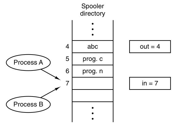
Imagine that our spooler directory has a large number of slots,
numbered 0, 1, 2, …, each one capable of holding a file name.
Also imagine that there are two shared variables,
out, which points to the next file to be printed, and
in, which points to the next free slot in the
directory.
These two variables might well be kept in a two-word file, available to
all processes.
At a certain instant, slots 0 to 3 are empty (the files have already
been printed),
and slots 4 to 6 are full (with the names of files to be printed).
More or less simultaneously,
processes A and B decide they want to queue a file for printing.
This is show below:
However, issues can occur, for example:
Process A reads in and stores the value, 7,
in a local variable called next_free_slot.
Just then, a clock interrupt occurs,
and the CPU decides that process A has run long enough,
so it switches to process B.
Process B also reads in, and also gets a 7,
so it stores the name of its file in slot 7,
and updates in to be an 8.
Then it goes off and does other things.
Eventually, process A runs again,
starting from the place it left off last time.
It looks at next_free_slot, finds a 7 there,
and writes its file name in slot 7,
erasing the name that process B just put there.
Then it computes next_free_slot + 1,
which is 8, and sets in to 8.
The spooler directory is now internally consistent,
so the printer daemon will not notice anything wrong,
but process B will never receive any output.
Situations like this,
where two or more processes are reading or writing some shared
data,
and the final result depends on who runs precisely when,
are called race conditions.
Debugging programs containing race conditions is no fun at all.
The results of most test runs are fine,
but rarely something weird and unexplained happens.
https://en.wikipedia.org/wiki/Mutual_exclusion
How do we avoid race conditions?
The key to preventing trouble here,
and in many other situations involving shared resources,
shared memory, shared files, and shared everything else,
is to prohibit concurrent access to shared resources,
prohibiting more than one process from reading and writing shared data
at the same time.
What we need is mutual exclusion.
If one process is using a shared variable or file,
the other processes should be excluded from doing the same.
The difficulty above occurred, because of concurrent shared
access:
Process B started using one of the shared variables,
before process A was finished with it.
We must choose appropriate primitive operations for achieving mutual
exclusion.
https://en.wikipedia.org/wiki/Critical_section
The problem of avoiding race conditions can be formulated
abstractly.
Part of the time, a process is busy doing computations on it’s own
data,
and other things that do not lead to race conditions.
However, sometimes a process may be accessing shared memory or
files.
There are parts of the program where the shared memory is
accessed.
These are called the critical regions or
critical sections.
Making sure two processes are ever in their critical regions at the same
time,
avoids race conditions.
This requirement of avoiding concurrent access to critical regions
avoids race conditions.
However, parallel processes can’t always cooperate correctly and
efficiently using shared data.
For efficiency, we want four conditions to hold,
to have a good solution:
The behavior that we want is shown:
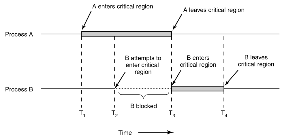
Here process A enters its critical region at time T1.
A little later, at time T2 process B attempts to enter its
critical region,
but fails because another process is already in its critical
region,
and we allow only one at a time.
Consequently, B is temporarily suspended until time T3,
when A leaves its critical region,
allowing B to enter immediately.
Eventually B leaves (at T4),
and we are back to the original situation,
with no processes in their critical regions.
+++++++++++++++++++ Cahoot-02-4
We now examine various proposals for achieving mutual
exclusion,
so that while one process is busy updating shared memory, in its
critical region,
no other process will enter its critical region and cause trouble.
Several mechanisms follow:
One simple solution is to have each process disable all
interrupts,
just after entering its critical region,
and re-enable them just before leaving it.
With interrupts disabled, no clock interrupts can occur.
The CPU is only switched from process to process,
as a result of clock or other interrupts.
With interrupts turned off,
the CPU will not be switched to another process.
Thus, once a process has disabled interrupts,
it can examine and update the shared memory,
without fear that any other process will intervene.
However, it is unwise to give user processes the power to turn off
interrupts.
Suppose that one of them did,
and then never turned them on again?
That could be the end of the system.
Further, if the system is a multiprocessor, with two or more
CPUs,
disabling interrupts affects only the CPU that executed the disable
instruction.
The other ones will continue running and can access the shared
memory.
The kernel itself can disable interrupts for a few
instructions,
while it is updating variables or lists.
Why?
For example,
if an interrupt occurred while the list of ready processes was in an
inconsistent state,
race conditions could occur.
Disabling interrupts is often a useful technique within the operating
system itself,
but is not appropriate as a general mutual exclusion mechanism for user
processes.
https://en.wikipedia.org/wiki/Lock_(computer_science)
As a second attempt, let us look for a software solution.
Consider having a single, shared, (lock) variable, initially 0.
When a process wants to enter its critical region,
it first tests the lock.
If the lock is 0,
then the process sets it to 1,
and enters the critical region.
If the lock is already 1,
then the process just waits until it becomes 0.
Lock of 0 means that no process is in its critical region,
and a 1 means that some process is in its critical region.
Unfortunately, this idea contains the same fatal flaw,
which we saw in the spooler directory example above.
Suppose that one process reads the lock, and sees that it is 0.
Before it can set the lock to 1,
another process is scheduled, runs, and sets the lock to 1.
When the first process runs again,
it will also set the lock to 1,
and two processes will be in their critical regions at the same
time.
Even first reading out the lock value,
and checking it again just before storing into it,
does not help.
The race now occurs if the second process modifies the lock,
just after the first process has finished its second check.
A third approach to the mutual exclusion problem is shown below:
while (TRUE) {
    while (turn != 0) /* empty loop */ ;
    critical_region();
    turn = 1;
    noncritical_region();
}
while (TRUE) {
while (turn != 1) /* empty loop */ ;
critical_region();
turn = 0;
noncritical_region();
}In both cases, be sure to note the semicolons terminating the while
statements.
In the code above, the integer variable turn, initially
0,
keeps track of whose turn it is, to enter the critical region,
and examining or updating the shared memory.
Initially, process 0 inspects turn, finds it to be 0,
and enters its critical region.
Process 1 also finds it to be 0,
and therefore sits in a tight loop,
continually testing turn to see when it becomes 1.
Side note:
Continuously testing a variable until some value appears is called
busy waiting.
It should usually be avoided, since it wastes CPU time.
Only when the wait will be short is busy waiting usually used.
A lock that uses busy waiting is called a spin
lock.
When process 0 leaves the critical region, it sets turn to 1,
to allow process 1 to enter its critical region.
Suppose that process 1 finishes its critical region quickly,
so both processes are in their noncritical regions,
with turn set to 0.
Now process 0 executes its whole loop quickly,
exiting its critical region and setting turn to 1.
At this point turn is 1,
and both processes are executing in their noncritical regions.
Suddenly, process 0 finishes its noncritical region,
and goes back to the top of its loop.
Unfortunately, it is not permitted to enter its critical region
now,
because turn is 1 and process 1 is busy with its noncritical
region.
It hangs in its while loop until process 1 sets turn to 0.
When one of the processes is much slower than the other,
taking turns is not good for efficiency.
This situation violates condition 3 set out above:
process 0 is being blocked by a process not in its critical region.
Going back to the spooler directory discussed above,
if we now associate the critical region with reading and writing the
spooler directory,
process 0 would not be allowed to print another file,
because process 1 was doing something else.
This solution requires that the two processes strictly
alternate,
in entering their critical regions.
For example, in spooling files,
neither one would be permitted to spool two in a row.
While this algorithm does avoid all races,
it is not really a serious candidate as a solution,
because it violates condition 3 and is bad for efficiency.
In 1981, GL Peterson discovered a simpler way to achieve mutual
exclusion,
This algorithm consists of two procedures written in ANSI C,
which means that function prototypes should be supplied,
for all the functions defined and used.
To save space, we will not show the prototypes in this or subsequent
examples.
#define FALSE 0
#define TRUE 1
#define N 2                       /* number of processes */

int turn;                         /* whose turn is it? */
int interested[N];                /* all values initially 0 (FALSE) */

void enter_region(int process) {  /* process is 0 or 1 */
    int other;                    /* number of the other process */
    other = 1 - process;          /* the opposite of process */
    interested[process] = TRUE;   /* show that you are interested */
    turn = process;               /* set flag */
    while (turn == process && interested[other] == TRUE) /* spin */ ;
}

void leave_region(int process) {  /* process: who is leaving */
    interested[process] = FALSE;  /* indicate departure from critical region */
}
Before using the shared variables
(i.e., before entering its critical region),
each process calls enter_region(process_number),
with its own process number, 0 or 1, as the
parameter.
This call will cause it to wait, if need be, until it is safe to
enter.
After it has finished with the shared variables,
the process calls leave_region(process_number) to indicate
that it is done,
and to allow the other process to enter, if it so desires.
Initially, neither process is in its critical region:
Now process 0 calls enter_region.
0 indicates its interest by setting its array
element,
and sets turn to 0.
Since process 1 is not interested,
enter_region returns immediately.
If process 1 now calls enter_region,
1 will hang there until interested[0] goes to
FALSE,
an event that only happens when process 0 calls
leave_region,
to exit the critical region.
Now consider the case that both processes call
enter_region almost simultaneously.
Both will store their process number in turn.
The first one is lost (overwritten).
Suppose that process 0 is first,
and 1 stores afterwards, so turn is
1.
When both processes come to the while statement,
process 0 executes it zero times and enters its critical
region.
Process 1 loops, and does not enter its critical
region.
Now let us look at another proposal,
that requires a little help from the hardware.
Many computers, including with multiple processors in mind,
have an extra assembly instruction provided by the architecture:
TSL RX,LOCK
(Test and Set Lock) that works as follows:
it reads the contents of the memory word LOCK into register
RX,
and then stores a nonzero value at the memory address
LOCK.
Both operations of reading the word, and storing into it,
are guaranteed to be indivisible (executed together).
No other processor can access the memory word,
until the instruction is finished.
The CPU executing the TSL instruction, locks the memory
bus,
to prohibit other CPUs from accessing memory until it is done.
To use the TSL instruction, we will use a shared variable,
LOCK, to coordinate access to shared memory.
When LOCK is 0,
any process may set it to 1 using the TSL
instruction,
and then read or write the shared memory.
When it is done, the process sets LOCK back to
0,
using an ordinary move instruction.
How can this instruction be used,
to prevent two processes from simultaneously entering their critical
regions?
Entering and leaving a critical region using the TSL instructions in assembly pseudocode:
enter_region:
    TSL REGISTER,LOCK  | copy LOCK to register, and set LOCK to 1
    CMP REGISTER,#0    | was LOCK zero?
    JNE ENTER_REGION   | if it was non zero, then LOCK was set, so loop
    RET                | return to caller; critical region entered

leave_region:
    MOVE LOCK,#0       | store a 0 in LOCK
    RET                | return to caller
The user must use these functions correctly,
before and after entering and leaving critical regions.
If they do not, for whatever reason,
race conditions can still occur.
The first instruction copies the old value of LOCK to
the register,
and then sets LOCK to 1.
Then the old value is compared with 0.
If it is nonzero, the lock was already set,
so the program just goes back to the beginning,
and tests it again.
When the process currently in its critical region,
is done with its critical region,
the LOCK will become 0
and the subroutine returns, with the lock set.
Clearing the lock is simple.
The program just stores a 0 in LOCK.
No special instructions are needed.
One solution to the critical region problem is now
straightforward.
Before entering its critical region,
a process calls enter_region,
which does busy waiting until the LOCK is free;
then it acquires the lock and returns.
After the critical region, the process calls
leave_region,
which stores a 0 in LOCK.
As with all solutions based on critical regions,
for the method to work,
the processes must call enter_region and
leave_region at the correct times.
If a process cheats, the mutual exclusion will fail.
Both Peterson’s solution, and TSL, are correct.
However, both are inefficient, because they requiring busy waiting.
In essence, what these solutions do is this:
When a process wants to enter its critical region,
it checks to see if the entry is allowed.
If it is not, the process just spins in a tight loop waiting until it
is.
Not only does this approach waste CPU time,
but it can also have unexpected effects.
https://en.wikipedia.org/wiki/Priority_inversion
Consider a computer with two processes,
H, with high priority and
L, with low priority,
which share a critical region.
The scheduling rules specify that:
H is run whenever it is in ready state.
At a certain moment, with L in its critical
region,
H becomes ready to run
(e.g., an I/O operation completes).
H now begins busy waiting,
but since L is never scheduled while H is
running,
L never gets the chance to leave its critical
region,
so H loops forever.
This situation is sometimes referred to as the priority inversion problem.
Now let us look at some inter-process communication primitives,
that block and wait, instead of wasting CPU time,
when they are not allowed to enter their critical regions.
One of the simplest is the pair, sleep and
wakeup.
sleep is a system call that causes the caller to
block,
that is, be suspended until another process wakes it up.
The wakeup system call has one parameter,
the process to be awakened.
Alternatively, both sleep and wakeup can
each have one parameter,
a memory address used to match up sleeps with wakeups.
https://en.wikipedia.org/wiki/Producer-consumer_problem
This can be considered an abstract model of IPC,
recall the problem of sequencing mentioned above.
As an example of how these primitives can be used in practice,
let us consider the producer-consumer problem
(also known as the bounded buffer problem).
Two processes share a common, fixed-size buffer.
One of them, the producer, puts information into the buffer,
and the other one, the consumer, takes it out.
It is also possible to generalize the problem,
to have m producers and n consumers,
but we will only consider the case of one producer and one
consumer,
This assumption simplifies the solutions.
Trouble arises when the producer wants to put a new item in the
buffer,
but the buffer is already full.
The solution is for the producer to go to sleep,
to be awakened when the consumer has removed one or more items.
Similarly, if the consumer wants to remove an item from the
buffer,
and sees that the buffer is empty,
then it goes to sleep until the producer puts something in the
buffer,
and wakes it up.
This approach sounds simple enough,
but it leads to the same kinds of race conditions as earlier,
with the spooler directory.
To keep track of the number of items in the buffer,
we will need a variable, count.
If the maximum number of items the buffer can hold is N,
then the producer’s code will first test to see if count is
N.
If it is, then the producer will go to sleep;
if it is not, then the producer will add an item,
and increment count.
The consumer’s code is similar:
first test count, to see if it is 0.
If it is, go to sleep;
if it is nonzero, remove an item,
and decrement the counter.
Each of the processes also tests to see if the other should be
sleeping,
and if not, wakes it up.
The code for both producer and consumer is shown below:
The problem is the same,
two operations in a critical region,
which can be multi-tasked on by the CPU.
Thus, this producer-consumer solution below also has a fatal race
condition:
#define N 100                                 /* number of slots in the buffer */
int count = 0;                                /* number of items in the buffer */
void producer(void) {
    int item;
    while (TRUE) {                            /* repeat forever */
        item = produce_item();                /* generate next item */
        if (count == N) sleep();              /* if buffer is full, go to sleep */
        insert_item(item);                    /* put item in buffer */
        count = count + 1;                    /* increment count of items in buffer */
        if (count == 1) wakeup(consumer);     /* was buffer empty? */
    }
}
void consumer(void) {
    int item;
    while (TRUE) {                            /* repeat forever */
        if (count == 0) sleep();              /* if buffer is empty, got to sleep */
        item = remove_item();                 /* take item out of buffer */
        count = count - 1;                    /* decrement count of items in buffer */
        if (count == N - 1) wakeup(producer); /* was buffer full? */
        consume_item(item);                   /* print item */
    }
}
To express system calls such as sleep and
wakeup in C,
we will show them as calls to library routines.
They are not part of the standard C library,
but presumably would be available on any system that actually had these
system calls.
The procedures enter_item and
remove_item,
definitions of which are not shown,
handle the bookkeeping of putting items into the buffer,
and taking items out of the buffer.
The race condition can occur,
because access to count is unconstrained.
The buffer is empty,
and the consumer has just read count, to see
if it is 0.
At that instant,
the scheduler decides to stop running the consumer,
and start running the producer.
The producer enters an item in the buffer,
increments count, and notices that it is now 1.
Reasoning that count was just 0,
and thus the consumer must be sleeping,
the producer calls wakeup to wake the
consumer up.
Unfortunately, the consumer is not yet logically asleep,
so the wakeup signal is lost.
When the consumer next runs,
it will test the value of count it previously read,
find it to be 0, and go to sleep.
Sooner or later the producer will fill up the buffer,
and also go to sleep.
Both will sleep forever.
A wakeup sent to a process,
that is not (yet) sleeping, is lost.
If it were not lost, then it would work.
A quick fix is to modify the rules,
to add a wakeup_waiting_bit to the picture.
When a wakeup is sent to a running process,
that is still awake, this bit is set.
Later, when the process tries to go to sleep,
if the wakeup_waiting_bit is on,
then it will be turned off,
but the process will stay awake.
The wakeup_waiting_bit is a piggy bank for
wakeup signals.
While this saves the day in this simple example,
it is easy to construct examples with three or more processes,
in which one wakeup_waiting_bit is insufficient.
We could make another patch, and add a second,
wakeup_waiting_bit2,
or maybe 8 or 32 of them, but in principle the problem is still
there…
https://en.wikipedia.org/wiki/Semaphore_(programming)
Dijkstra (1965) suggested using an integer variable,
to count the number of wakeups, saved for future use.
He named such an integer a semaphore.
A semaphore could have the value 0,
indicating that no wakeups were saved,
or some positive value,
if one or more wakeups were pending.
Dijkstra proposed defining two multi-part operations,
down and up
(which are generalizations of sleep and
wakeup, respectively).
down
The down operation on a semaphore checks if the value is greater than
0.
If so, it decrements the value (i.e., consumes one stored wakeup)
and just continues.
If the value is 0, then the process is put to sleep,
without completing the down operation.
This happens later, by a different process.
Checking the value, changing it, and possibly going to sleep,
must all done as a single, indivisible, atomic action.
It must be guaranteed that once a semaphore operation has started,
no other process can access the semaphore,
until the operation has completed or blocked.
In solving synchronization problems and avoiding race conditions,
This atomicity is absolutely essential.
up
The up operation increments the value of the semaphore addressed.
If one or more processes were sleeping on that semaphore,
unable to complete an earlier down operation,
one of them is chosen by the system (e.g., at random),
and is allowed to complete its down.
Thus, after an up on a semaphore, with processes sleeping
on it,
the semaphore will still be 0,
but there will be one fewer process sleeping on it.
The operation of incrementing the semaphore,
and waking up one process, must also be indivisible.
No process must ever block doing an up operation,
just as in the earlier model,
where no process ever blocks when doing a wakeup.
As an aside, in Dijkstra’s original paper,
he used the names p and v instead of down and up, respectively,
but since these have no mnemonic significance to people who do not speak
Dutch
(and only marginal significance to those who do),
we will use the names down and up instead.
It is essential that they be implemented in an indivisible way.
The normal way is to implement up and down as
system calls,
with the operating system briefly disabling all interrupts while it
is:
testing the semaphore,
updating it,
and if necessary, putting the process to sleep.
Since these several actions take only a few instructions,
no harm is done in disabling interrupts.
If multiple CPUs are being used,
each semaphore itself should be protected by a lock variable,
with the TSL instruction used,
to make sure that only one CPU at a time examines the semaphore.
We use TSL to prevent several CPUs from accessing the
semaphore at the same time.
This is quite different from a spin lock,
busy waiting by the producer for space in the buffer,
or consumer waiting, for the other to empty or load the buffer.
The distinction is in the duration of time.
The semaphore operation only takes a few microseconds,
whereas the producer or consumer might take arbitrarily long.
The multiple operations in up and down
themselves must be indivisible.
We use TSL to accomplish this, as above.
Below, we do not show those implementation of up and
down,
but assume they are correct, and apply them.
The code below illustrates two ways up and down can be used.
First, two semaphores are used for the producer-consumer problem.
Second, up and down with a binary lock can
be used to efficiently protect regions,
that themselves are critical, but may take longer than a
semaphore,
in which case, we may call it a mutex instead.
#define N 100                   /* number of slots in the buffer */
typedef int semaphore;          /* semaphores are a special kind of int */
semaphore mutex = 1;            /* controls access to critical region */
semaphore empty = N;            /* counts empty buffer slots */
semaphore full = 0;             /* counts full buffer slots */

void producer(void) {
    int item;
    while (TRUE) {              /* TRUE is the constant 1 */
        item = produce_item();  /* generate something to put in buffer */
        down(&empty);           /* decrement empty count */
        down(&mutex);           /* enter critical region */
        insert_item(item);      /* put new item in buffer */
        up(&mutex);             /* leave critical region */
        up(&full);              /* increment count of full slots */
    }
}

void consumer(void) {
    int item;
    while (TRUE) {              /* infinite loop */
        down(&full);            /* decrement full count */
        down(&mutex);           /* enter critical region */
        item = remove_item();   /* take item from buffer */
        up(&mutex);             /* leave critical region */
        up(&empty);             /* increment count of empty slots */
        consume_item(item);     /* do something with the item */
    }
}
Reminder: this is not the implementation of the semaphore
itself,
but the utilization of it for a similar purpose.
This solution uses three indivisible integers,
one called full,
for counting the number of slots that are full,
one called empty,
for counting the number of slots that are empty,
and one called mutex,
to make sure the producer and consumer do not access the buffer at the
same time.
up and down as semaphores guarantees their
updates to these ints are indivisible.
full is initially 0,
empty is initially equal to the number of slots in the
buffer,
and mutex is initially 1.
Binary semaphores are initialized to 1,
and used by two or more processes,
to ensure that only one of them can enter its critical region at the
same time.
If each process does a down operation just before entering
its critical region,
and an up just after leaving it,
then mutual exclusion to the shared data is guaranteed.
Producer consumer as a model of IPC
Now that we have a good inter-process communication primitive at our
disposal,
recall the example interrupt sequence we covered above,
Generalizing previous disk access interrupt example above:
In a system using semaphores,
the natural way to hide interrupts is to have a mutex semaphore,
initially set to 0, associated with each I/O device.
Just after starting an I/O device,
the managing process does a down operation on the
associated semaphore,
thus blocking immediately.
When the interrupt comes in,
the interrupt handler then does an up operation on the
associated semaphore,
which makes the relevant process ready to run again.
Step 6 in the image above,
consists of doing an up on the device’s semaphore,
so that in step 7 the scheduler will be able to run the device
manager.
If several processes are now ready,
then the scheduler may choose to run an even more important process
next.
We will look at how scheduling is done later in this chapter.
In the example code above,
we have actually used semaphores in two different ways.
This difference is important to make explicit.
Synchronization:
One use of semaphores is for synchronization.
Both the full and empty semaphores are needed,
to guarantee that certain event sequences do or do not occur:
They ensure that the producer stops running when the buffer is
full,
and the consumer stops running when it is empty.
Second, use of semaphores for mutual exclusion,
is different.
Mutual exclusion:
The mutex semaphore is used for accomplishing efficient
mutual exclusion.
It is designed to guarantee that only one process at a time,
will be reading or writing shared data,
the buffer, and the associated variables.
This mutual exclusion is required to prevent chaos,
caused by concurrent editing of a shared resource.
https://en.wikipedia.org/wiki/Lock_(computer_science)
When the semaphore’s ability to count is not needed,
a simplified version of the semaphore is called a mutex.
Mutexes are good only for managing mutual exclusion,
to some shared resource or piece of code.
They are easy and efficient to implement,
which makes them especially useful,
They are often used in non-kernel thread packages,
that are implemented entirely in user space.
A mutex is a variable that can be in one of two states:
unlocked or locked.
Consequently, only 1 bit is required to represent it,
but in practice, an integer often is used,
with 0 meaning unlocked,
and all other values meaning locked.
Two procedures are used with mutexes.
lock
When a process (or thread) needs access to a critical region,
it calls mutex_lock.
If the mutex is currently unlocked,
meaning that the critical region is available,
the call succeeds,
and the calling thread is free to enter the critical region.
unlock
If the mutex is already locked,
then the caller is blocked,
until the process in the critical region is finished,
and calls mutex_unlock.
If multiple processes are blocked on the mutex,
then one of them is chosen at random,
and allowed to acquire the lock.
Both lock and unlock operations may be
implemented with TSL.
But, they are different than TSL itself,
because they add the feature of blocking/sleeping/suspending.
https://en.wikipedia.org/wiki/Monitor_(synchronization)
Deadlocks
When programming the above example,
It is easy to make mistakes.
In the semaphore code above,
look closely at the order of the down calls,
before entering or removing items from the buffer.
Suppose that the two down calls in the producer’s code were
reversed in order,
so mutex was decremented before empty, instead of after it.
If the buffer were completely full,
then the producer would block,
with mutex set to 0.
Consequently, the next time the consumer tried to access the
buffer,
it would do a down on mutex, now 0, and block
too.
Both processes would stay blocked forever,
and no more work would ever be done.
This unfortunate situation is called a deadlock.
We will study deadlocks later!
This problem is pointed out,
to show how careful you must be when using semaphores.
One subtle error, and everything comes to a grinding halt.
It is like programming in assembly language,
only worse, because the errors are race conditions, deadlocks,
and other forms of unpredictable and irreproducible behavior.
Monitors:
To make it easier to write correct programs,
we can use higher level synchronization primitive called a monitor.
A monitor is a collection of procedures, variables, and data
structures,
that are all grouped together in a special kind of module or
package.
Processes may call the procedures in a monitor whenever they want
to,
but they cannot directly access the monitor’s internal data
structures,
from procedures declared outside the monitor.
Below, we illustrate a monitor,
written in an imaginary language, Pidgin Pascal:
monitor example
    integer i;
    condition c;

    procedure producer(x);
    .
    .
    .
    end;

    procedure consumer(x);
    .
    .
    .
    end;
end monitor;
Monitors have a key property that makes them useful for achieving
mutual exclusion:
only one process can be active in a monitor at any instant.
Monitors are a programming language construct,
so the compiler knows they are special,
and can handle calls to monitor procedures,
differently from other procedure calls.
Typically, when a process calls a monitor procedure,
the first few instructions of the procedure will perform a check,
to see if any other process is currently active within the
monitor.
If so, the calling process will be suspended,
until the other process has left the monitor.
If no other process is using the monitor,
the calling process may enter.
The compiler implements the mutual exclusion on monitor
entries.
A common way is to use a mutex or binary semaphore.
However, because the compiler, not the programmer,
arranges for the mutual exclusion,
it is much less likely that something will go wrong.
By merely turning all the critical regions into monitor
procedures,
no two processes will ever execute their critical regions at the same
time.
Efficiency
Although monitors provide an easy way to achieve mutual exclusion,
as we have seen above, that is not enough for efficiency.
We also need a way for processes to block, when they cannot
proceed.
In the producer-consumer problem,
it is easy enough to put all the tests for buffer-full and buffer-empty
in monitor procedures,
but how should the producer block, when it finds the buffer full?
Wait and Signal
The solution is to have:
condition variables,
and two operations on them, wait and
signal.
When a monitor procedure discovers that it cannot continue
(e.g., the producer finds the buffer full),
then it does a wait on some condition variable, say,
full.
This action causes the calling process to block.
Another process that had been previously prohibited from entering the
monitor,
is now allowed to enter it.
This other process, for example, the consumer,
can wake up its sleeping partner,
by sending a signal on the condition variable that its partner is
waiting on.
To avoid having two active processes in the monitor at the same
time,
we need a rule telling what happens after a signal.
One solution is to let the newly awakened process run,
suspending the other one.
A second solution requires any process sending a signal to exit the
monitor immediately.
A signal statement may appear only as the final statement in a monitor
procedure.
This proposal is conceptually simpler,
and is also easier to implement.
If a signal is sent on a condition variable,
on which several processes are waiting,
only one of them, determined by the system scheduler, is revived.
There is also a third solution,
This is to let the signaler continue to run,
and only after the signaler has exited the monitor,
then allow the waiting process to start running,
Condition variables are not counters.
They do not accumulate signals for later use the way semaphores
do.
If a condition variable is signaled with no one waiting on it,
then the signal is lost.
The wait must come before the signal.
This rule makes the implementation much simpler.
To accommodate for lost signals,
we keep track of the state of each process with variables, if need
be.
A process that might otherwise send a signal,
can see that this operation is not necessary,
by looking at the variables.
A skeleton of the producer-consumer problem with monitors is shown
below.
Only one monitor procedure at a time is active.
The buffer has N slots.
monitor ProducerConsumer
    condition full, empty;
    integer count;

    procedure insert(item: integer);
    begin
        if count = N then wait(full);
        insert_item(item);
        count := count + 1;
        if count = 1 then signal(empty)
    end;

    procedure remove: integer;
    begin
        if count = 0 then wait(empty);
        remove = remove_item;
        count := count 1;
        if count = N 1 then signal(full)
    end;

    count := 0;
end monitor;

procedure producer;
begin
    while true do
    begin
        item = produce_item;
        ProducerConsumer.insert(item)
    end
end;

procedure consumer;
begin
    while true do
    begin
        item = ProducerConsumer.remove;
        consume_item(item)
    end
end;
Operations wait and signal look similar to
sleep and wakeup,
which we saw earlier had possible fatal race conditions.
These now have one crucial difference:
sleep and wakeup failed because while one
process was trying to go to sleep,
the other one was trying to wake it up.
With monitors, that cannot happen.
The automatic mutual exclusion on monitor procedures guarantees
that,
if the producer inside a monitor procedure discovers that the buffer is
full,
it will be able to complete the wait operation,
without having to worry about the possibility that,
the scheduler may switch to the consumer just before the
wait completes.
The consumer will not even be let into the monitor at all,
until the wait is finished and the producer is marked as no longer
runnable.
Although Pidgin Pascal is an imaginary language,
some real programming languages also support monitors.
One such language is Java.
Java supports user-level threads,
and also allows methods (procedures) to be grouped together into
classes.
By adding the keyword synchronized to a method
declaration,
Java guarantees that once any thread has started executing that
method,
no other thread will be allowed to start executing any other
synchronized method in that class.
synchronized methods in Java differ from classical
monitors in an essential way:
Java does not have condition variables.
Instead, it offers two procedures, wait and
notify,
that are the equivalent of sleep and
wakeup,
except that when they are used inside synchronized
methods,
they are not subject to race conditions.
By making the mutual exclusion of critical regions automatic,
monitors make parallel programming much less error-prone than with
semaphores.
Still, they too have some drawbacks.
Monitors are a programming language concept.
The compiler must recognize them, and arrange for the mutual exclusion
somehow.
C, Pascal, and most other languages do not have monitors,
so it is unreasonable to expect their compilers to enforce any mutual
exclusion rules.
These same languages do not have semaphores either,
but adding semaphores is easy:
all you need to do is add two short assembly code routines to the
library,
to issue the up and down system calls.
The compilers do not even have to know that they exist.
Of course, the operating systems have to know about the
semaphores,
but at least if you have a semaphore-based operating system,
you can still write the user programs for it in C, C++ or FORTRAN.
With monitors, you need a language that has them built in.
Benefits:
Monitors and semaphores solve the mutual exclusion problem on one or
more CPUs,
that all have access to a common memory.
By putting the semaphores in the shared memory,
and protecting them with TSL instructions,
we can avoid races.
Problems:
When we go to a distributed system consisting of multiple CPUs,
each with its own private memory, connected by a local area
network,
these primitives become inapplicable.
None of the primitives provide for information exchange between
machines.
Semaphores are too low level,
Monitors only exist in a few programming languages.
Something else is needed.
+++++++++++++ Cahoot-02-5
That something else is message passing.
It can be used several ways:
between processes that do not share memory,
between a process and a server,
or between remote processes.
This method of inter-process communication uses two primitives,
send and receive, which, like semaphores, and
unlike monitors,
are system calls rather than language constructs.
As such, they can easily be put into library procedures,
such as:
send(destination, &message);
send sends a message to a given destination,
receive(source, &message);
receive receives a message from a given source
(or from ANY, if the receiver does not care).
If no message is available,
then the receiver could block until one arrives.
Alternatively, it could return immediately with an error code.
Message passing systems have many challenging problems and design
issues,
that do not arise with semaphores or monitors,
especially if the communicating processes are on different
machines,
connected by a network.
For example, messages can be lost by the network.
To guard against lost messages,
the sender and receiver can agree that as soon as a message has been
received,
the receiver will send back an acknowledgment message.
If the sender has not received the acknowledgment within a certain time
interval,
then it re-transmits the message.
Now consider what happens if the message itself is received
correctly,
but the acknowledgment is lost.
The sender will re-transmit the message,
so the receiver will get it twice.
Thus, it is essential that the receiver can distinguish a new
message,
from the re-transmission of an old one.
To do so, consecutive sequence numbers are included in each original
message.
If the receiver gets another message,
bearing the same sequence number as the previous message,
then it knows that the message is a duplicate that can be ignored.
Message systems must consider how processes are named,
so that the process specified in a send or
receive call is unambiguous.
Authentication is also an issue in message systems:
how can the client tell that they are communicating with the real file
server,
and not with an imposter?
There are also design issues that are important when the sender and receiver are on the same machine:
One of these is performance.
Copying messages from one process to another,
is slower than doing a semaphore operation, or entering a monitor,
or any of the previous shared memory systems.
Much work has gone into making message passing efficient.
Some have suggested limiting message size to what will fit in the
machine’s registers,
and then doing message passing using the registers.
Now let us see how the producer-consumer problem can be solved,
with message passing and no shared memory.
The producer-consumer problem with N messages.
#define N 100                       /* number of slots in the buffer */

void producer(void) {
    int item;
    message m;                      /* message buffer */
    while (TRUE) {
        item = produce_item();      /* generate something to put in buffer */
        receive(consumer, &m);      /* wait for an empty to arrive */
        build_message(&m, item);    /* construct a message to send */
        send(consumer, &m);         /* send item to consumer */
    }
}

void consumer(void) {
    int item, i;
    message m;
    for (i = 0; i < N; i++) send(producer, &m); /* send N empties */
    while (TRUE) {
        receive(producer, &m);                  /* get message containing item */
        item = extract_item(&m);                /* extract item from message */
        send(producer, &m);                     /* send back empty reply */
        consume_item(item);                     /* do some1thing with the item */
    }
}
We assume that all messages are the same size,
and that messages sent but not yet received,
are buffered automatically by the operating system.
In this solution, a total of N messages is used,
analogous to the N slots in a shared memory buffer.
The consumer starts out by sending N empty messages to the
producer.
Whenever the producer has an item to give to the consumer,
it takes an empty message and sends back a full one.
The total number of messages in the system remains constant in
time,
so they can be stored in a given amount of memory known in advance.
If the producer works faster than the consumer,
all the messages will end up full, waiting for the consumer;
the producer will be blocked, waiting for an empty to come
back.
If the consumer works faster, then the reverse happens:
all the messages will be empties,
waiting for the producer to fill them up;
the consumer will be blocked, waiting for a full
message.
Many variants are possible with message passing.
For starters, let us look at how messages are addressed:
One way is to assign each process a unique address,
and have messages be addressed to processes.
A second way is to invent a new data structure, called a
mailbox.
A mailbox is a place to buffer a certain number of messages,
typically specified when the mailbox is created.
The address parameters in the send and
receive calls are mailboxes, not processes.
When a process tries to send to a mailbox that is full,
it is suspended until a message is removed from that mailbox,
making room for a new one.
Both the producer and consumer would create mailboxes large enough to
hold N messages.
The producer would send messages containing data to the consumer’s
mailbox,
and the consumer would send empty messages to the producer’s
mailbox.
When mailboxes are used, the buffering mechanism is clear:
the destination mailbox holds messages sent to the destination
process,
that have not yet been accepted.
A third way is to eliminate all buffering.
If the send is done before the receive,
then the sending process is blocked until the receive happens,
at which time the message can be copied,
directly from the sender to the receiver,
with no intermediate buffering.
If the receive is done first,
the receiver is blocked until a send happens.
This strategy is often known as a rendezvous.
It is easier to implement than a buffered message scheme,
but is less flexible,
since the sender and receiver are forced to run in lockstep.
MINIX3 operating system uses the rendezvous method,
with fixed size messages for communication among processes.
User processes also use this method to communicate with operating system
components,
although a programmer does not see this,
since library routines mediate systems calls.
Inter-process communication in MINIX3 (and UNIX) is via pipes,
which are effectively mailboxes.
The only real difference between a message system with mailboxes,
and the pipe mechanism, is that pipes do not preserve message
boundaries.
If one process writes 10 messages of 100 bytes to a pipe,
and another process reads 1000 bytes from that pipe,
then the reader will get all 10 messages at once.
With a true message system, each read should return only one
message.
If the processes agree always to read and write fixed-size messages from
the pipe,
or to end each message with a special character (e.g., linefeed),
then no problems arise.
Message passing is commonly used in parallel programming
systems.
One well-known message-passing system, for example,
is MPI (Message-Passing Interface).
It is widely used for scientific computing.
++++++++ Cahoot-02-6
The operating systems literature is full of interprocess
communication problems,
that have been widely discussed using a variety of synchronization
methods.
We will examine two of the better-known problems.
In 1965, Dijkstra posed and solved a synchronization problem he
called the dining philosophers problem.
The problem can be stated quite simply as follows.
Five philosophers are seated around a circular table.
Each philosopher has a plate of spaghetti.
The spaghetti is so slippery that a philosopher needs two forks to eat
it.
Between each pair of plates is one fork.
The layout of the table is illustrated:

The life of a philosopher consists of alternate periods of eating and
thinking.
(This is something of a contrivance, even for philosophers,
but the other activities are irrelevant here…)
When a philosopher gets hungry,
they try to acquire a left and right fork,
one at a time, in either order.
If successful in acquiring two forks,
then they eat for a while,
and finally put down the forks and continue to think.
The key question is:
Can you write a program for each philosopher,
that does what it is supposed to do, and never gets stuck?
We show the obvious (incorrect) solution:
#define N 5                     /* number of philosophers */

void philosopher(int i) {       /* i: philosopher number, from 0 to 4 */
    while (TRUE) {
        think();                /* philosopher is thinking */
        take_fork(i);           /* take left fork */
        take_fork((i+1) % N);   /* take right fork; % is modulo operator */
        eat();                  /* Eat */
        put_fork(i);            /* put left fork back on the table */
        put_fork((i+1) % N);    /* put right fork back on the table */
    }
}
The procedure take_fork waits until the specified fork
is available,
and then seizes it.
Unfortunately, the obvious solution is wrong.
Suppose that all five philosophers take their left forks
simultaneously.
None will be able to take their right forks,
and there will be a deadlock.
We could modify the program, so that after taking the left
fork,
the program checks to see if the right fork is available.
If it is not, the philosopher puts down the left one,
waits for some time, and then repeats the whole process.
This proposal too, fails, although for a different reason.
With a little bit of bad luck,
all the philosophers could start the algorithm simultaneously,
picking up their left forks, seeing that their right forks were not
available,
putting down their left forks, waiting,
picking up their left forks again simultaneously, and so on,
forever.
A situation like this, in which all the programs continue to run
indefinitely,
but fail to make any progress is called starvation.
Now you might think,
“If the philosophers would just wait a random time,
instead of the same time,
after failing to acquire the right-hand fork,
then the chance that everything would continue in lockstep,
for even an hour, is very small.”
This observation is true, and in nearly all applications, trying again
later is not a problem.
For example, in a local area network (LAN) using Ethernet,
a computer sends a packet only when it detects no other computer is
sending one.
However, because of transmission delays,
two computers separated by a length of cable,
may send packets that overlap, a collision.
When a collision of packets is detected,
each computer waits a random time and tries again;
in practice this solution works fine.
In some applications one would prefer a solution that always
works,
and cannot fail due to an unlikely series of random numbers.
Think about safety control in a nuclear power plant.
One improvement to the solution above,
which has no deadlock and no starvation,
is to protect the five statements following the call to think,
by a binary semaphore.
Before starting to acquire forks,
a philosopher would do a down on mutex.
After replacing the forks, they would do an up on
mutex.
From a theoretical viewpoint, this solution is adequate.
From a practical one, it has a performance bug:
only one philosopher can be eating at any instant.
With five forks available,
we should be able to allow two philosophers to eat at the same
time,
as illustrated by this better solution:
#define N 5               /* number of philosophers */
#define LEFT (i+N-1)%N    /* number of i's left neighbor */
#define RIGHT (i+1)%N     /* number of i's right neighbor */
#define THINKING 0        /* philosopher is thinking */
#define HUNGRY 1          /* philosopher is trying to get forks */
#define EATING 2          /* philosopher is eating */
typedef int semaphore;    /* semaphores are a special kind of int */
int state[N];             /* array to keep track of everyone's state */
semaphore mutex = 1;      /* mutual exclusion for critical regions */
semaphore s[N];           /* one semaphore per philosopher */

void philosopher(int i) { /* i: philosopher number, from 0 to N−1 */
    while (TRUE) {        /* repeat forever */
        think();          /* philosopher is thinking */
        take_forks(i);    /* acquire two forks or block */
        eat();            /* eat spaghetti */
        put_forks(i);     /* put both forks back on table */
    }
}

void take_forks(int i) {  /* i: philosopher number, from 0 to N−1 */
    down(&mutex);         /* enter critical region */
    state[i] = HUNGRY;    /* record fact that philosopher i is hungry */
    test(i);              /* try to acquire 2 forks */
    up(&mutex);           /* exit critical region */
    down(&s[i]);          /* block if forks were not acquired */
}

void put_forks(i) {       /* i: philosopher number, from 0 to N−1 */
    down(&mutex);         /* enter critical region */
    state[i] = THINKING;  /* philosopher has finished eating */
    test(LEFT);           /* see if left neighbor can now eat */
    test(RIGHT);          /* see if right neighbor can now eat */
    up(&mutex);           /* exit critical region */
}

void test(i) {            /* i: philosopher number, from 0 to N−1 */
    if (state[i] == HUNGRY && state[LEFT] != EATING && state[RIGHT] != EATING) {
        state[i] = EATING;
        up(&s[i]);
    }
}
The solution presented above is deadlock-free,
and allows the maximum parallelism,
for an arbitrary number of philosophers.
It uses an array, state, to keep track of a philosopher’s
state,
eating, thinking, or hungry (trying to acquire forks).
A philosopher may move into eating state,
only if neither neighbor is eating.
Philosopher i’s neighbors are defined by the macros LEFT
and RIGHT.
In other words, if i is 2, LEFT is 1, and
RIGHT is 3.
The program uses an array of semaphores, one per philosopher,
so hungry philosophers can block, if the needed forks are busy.
Each process runs the procedure philosopher as its main
code,
but the other procedures, take_forks,
put_forks, and test,
are ordinary procedures, and not separate processes.
This problem models processes that are competing for exclusive
access,
to a limited number of resources, such as I/O devices,
or access to a database.
For example, imagine an airline reservation system,
with many competing processes wishing to read and write it.
It is acceptable to have multiple processes reading the database at the
same time,
but if one process is updating (writing) the database,
then no other process may have access to the database,
not even a reader.
The question is how do you program the readers and the writers?
One solution is shown:
typedef int semaphore;          /* rename int */
semaphore mutex = 1;            /* controls access to 'rc' */
semaphore db = 1;               /* controls access to the database */
int rc = 0;                     /* number of processes reading, or wanting to */

void reader(void) {
    while (TRUE) {              /* repeat forever */
        down(&mutex);           /* get exclusive access to 'rc' */
        rc = rc + 1;            /* one reader more now */
        if (rc == 1) down(&db); /* if this is the first reader */
        up(&mutex);             /* release exclusive access to 'rc' */
        read_data_base( );      /* access the data */
        down(&mutex);           /* get exclusive access to 'rc' */
        rc = rc − 1;            /* one reader fewer now */
        if (rc == 0) up(&db);   /* if this is the last reader */
        up(&mutex);             /* release exclusive access to 'rc' */
        use_data_read( );       /* noncritical region */
    }
}

void writer(void) {
    while (TRUE) {              /* repeat forever */
        think_up_data( );       /* noncritical region */
        down(&db);              /* get exclusive access */
        write_data_base( );     /* update the data */
        up(&db); /* release exclusive access */
    }
}
The first reader to get access to the database,
does a down on the semaphore db.
Subsequent readers merely have to increment a counter,
rc.
As readers leave, they decrement the counter, rc,
and the last one out, does an up on the semaphore,
allowing a blocked writer, if there is one, to get in.
The solution presented here implicitly contains a subtle
decision:
Suppose that while a reader is using the database,
another reader comes along.
Since having two readers at the same time is not a problem,
the second reader is admitted.
A third and subsequent readers can also be admitted.
Now suppose that a writer comes along.
The writer cannot be admitted to the data base,
since writers must have exclusive access,
so the writer is suspended.
Later, additional readers show up.
As long as at least one reader is still active,
subsequent readers are admitted.
As a consequence of this strategy,
as long as there is a steady supply of readers,
they will all get in as soon as they arrive.
The writer will be kept suspended, until no reader is present.
If a new reader arrives, say, every 2 seconds,
and each reader takes 5 seconds to do its work,
then the writer will never get in.
To prevent this situation,
the program could be written slightly differently:
When a reader arrives, and a writer is waiting,
the reader is suspended, behind the writer,
instead of being admitted immediately.
A writer has to wait for current readers,
that were active when it arrived, to finish,
but a writer does not have to wait for readers that came along after
it.
The disadvantage of this solution,
is that it achieves less concurrency, and thus lower performance.
There are other solutions that gives priority to writers.
++++++++ Cahoot-02-7
In the examples of the previous sections,
we have often had situations in which two or more processes
(e.g., producer and consumer) were logically runnable.
When a computer is multi-programmed,
it frequently has multiple processes competing for the CPU at the same
time.
When more than one process is in the ready state,
and there is only one CPU available,
the operating system must decide which process to run first.
The part of the operating system deciding is called the
scheduler;
the algorithm it uses is called the scheduling
algorithm.
Many scheduling issues apply both to processes and threads.
Initially, we will focus on process scheduling,
but later we will take a brief look at some issues specific to thread
scheduling.
Back in the old days of batch systems,
with input in the form of card images on a magnetic tape,
the scheduling algorithm was simple:
just run the next job on the tape.
With time-sharing systems, the scheduling algorithm became more
complex,
because there were generally multiple users waiting for service.
There may be one or more batch streams as well
(e.g., at an insurance company, for processing claims).
On a personal computer, you might think there would be only one active
process.
After all, a user entering a document on a word processor,
is unlikely to be simultaneously compiling a program in the
background.
However, there are often background jobs,
such as e-mail daemons sending or receiving e-mail.
You might also think that computers have gotten so much faster over the
years,
that the CPU is rarely a scarce resource any more.
However, new applications tend to demand more resources.
Processing digital photographs, or watching real time video, are
examples.
Nearly all processes alternate between two ends of a spectrum,
bursts of computing-intensive and (disk) I/O intensive processing,
as shown below:
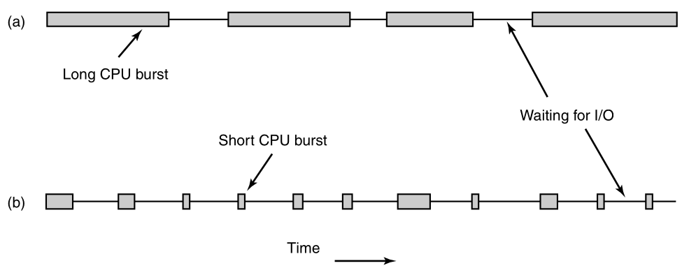
Typically the CPU runs for a while without stopping,
then a system call is made to read from a file or write to a file.
When the system call completes, the CPU computes again,
until it needs more data, or has to write more data, and so on.
Note that some I/O activities count as computing.
For example, when the CPU copies bits to a video RAM to update the
screen,
it is computing, not doing I/O, because the CPU is in use.
I/O in this sense is when a process enters the blocked state,
waiting for an external device to complete its work.
The important thing to notice about the image above is that some
processes,
such as the one in (a), spend most of their time computing,
while others, such as the one in (b), spend most of their time waiting
for I/O.
The former are called compute-bound;
the latter are called I/O-bound.
Compute-bound processes typically have long CPU bursts,
and thus infrequent I/O waits,
whereas I/O bound processes have short CPU bursts,
and thus frequent I/O waits.
The key factor is the length of the CPU burst,
not the length of the I/O burst.
I/O bound processes are I/O bound,
because they do not compute much between I/O requests,
not because they have especially long I/O requests.
It takes the same time to read a disk block,
no matter how much or how little time it takes to process the
data,
after they arrive.
There are a variety of situations in which scheduling may
occur.
First, scheduling is absolutely required on two occasions:
In each of these cases,
the process that had most recently been running becomes unready,
so another must be chosen to run next.
There are three other occasions when scheduling is usually done,
although logically it is not absolutely necessary at these times:
In the case of a new process,
it makes sense to re-evaluate priorities at this time.
The parent process may be able to request a different priority for its
child.
In the case of an I/O interrupt,
this usually means that an I/O device has now completed its work.
So some process that was blocked waiting for I/O,
may now be ready to run.
In the case of a clock interrupt,
this is an opportunity to decide whether the currently running process
has run too long.
Scheduling algorithms can be divided into two categories,
with respect to how they deal with clock interrupts:
A non-preemptive scheduling algorithm picks a process to run,
and then just lets it run until it blocks
(either on I/O or waiting for another process)
or until it voluntarily releases the CPU.
In contrast, a preemptive scheduling algorithm picks a process,
and lets it run for a maximum of some fixed time.
If it is still running at the end of the time interval,
then it is suspended,
and the scheduler picks another process to run (if one is
available).
Doing preemptive scheduling requires having a clock interrupt
occur,
at the end of a time interval,
to give control of the CPU back to the scheduler.
If no clock is available,
then non-preemptive scheduling is the only option.
Not surprisingly, in different environments,
different scheduling algorithms are needed.
This situation arises, because different application areas
(and different kinds of operating systems) have different goals.
That which the scheduler should optimize for,
is not the same in all systems.
Three environments worth distinguishing are
There are no users impatiently waiting at their terminals for a quick
response.
Consequently, acceptable solutions include:
non-preemptive algorithms,
or preemptive algorithms with long time periods for each process.
This approach reduces process switches and thus improves
performance.
In an environment with interactive users, preemption is
essential,
to keep one process from hogging the CPU, and denying service to the
others.
Even if no process intentionally ran forever, due to a program
bug,
then one process might shut out all the others indefinitely.
Preemption is needed to prevent this behavior.
In systems with real-time constraints, preemption is sometimes not
needed,
because the processes know that they may not run for long periods of
time,
and usually do their work and block quickly.
The difference with interactive systems,
is that real-time systems run only related programs,
that are intended to further the application at hand.
Interactive systems are general purpose,
and may run arbitrary programs,
that are not cooperative or even malicious.
In order to design a scheduling algorithm,
it is necessary to have some idea of what a good algorithm should
do.
Some goals depend on the environment (batch, interactive, or real
time),
but there are also some that are desirable in all cases.
Some goals of the scheduling algorithm under different
circumstances:
All systems
Fairness - giving each process a fair share of the CPU
Policy enforcement - seeing that stated policy is carried out
Balance - keeping all parts of the system busy
Batch systems
Throughput - maximize jobs per hour
Turnaround time - minimize time between submission and termination
CPU utilization - keep the CPU busy all the time
Interactive systems
Response time - respond to requests quickly
Proportionality - meet users’ expectations
Real-time systems
Meeting deadlines - avoid losing data
Predictability - avoid quality degradation in multimedia systems
Some goals occur on all systems:
Fairness
Under all circumstances, fairness is important.
Comparable processes should get comparable service.
Giving one process much more CPU time, than an equivalent one, is not
fair.
Of course, different categories of processes may be treated
differently.
Think of safety control, and doing the payroll,
both at a nuclear reactor’s computer center.
Policy
Somewhat related to fairness, is enforcing the system’s policies.
If the local policy is that,
safety control processes get to run whenever they want to,
even if it means the payroll is 30 sec late,
then the scheduler has to make sure this policy is enforced.
Balance / business
Another general goal is keeping all parts of the system busy, when
possible.
If the CPU and all the I/O devices can be kept running all the
time,
more work gets done per second,
than if some of the components are idle.
In a batch system, for example,
the scheduler has control of which jobs are brought into memory to
run.
Having some CPU-bound processes, and some I/O-bound processes,
both in memory together, is a better idea,
than first loading and running all the CPU-bound jobs,
and then when they are finished,
loading and running all the I/O-bound jobs.
If the latter strategy is used,
then when the CPU-bound processes are running,
they will fight for the CPU and the disk will be idle.
Later, when the I/O-bound jobs come in,
they will fight for the disk and the CPU will be idle.
It is better to keep the whole system running at once,
with a careful mix of processes.
The managers of corporate computer centers that run many batch
jobs
(e.g., processing insurance claims) typically look at three
metrics,
to see how well their systems are performing:
throughput, turnaround time, and CPU utilization.
Throughput
Throughput is the number of jobs per second that the system
completes.
All things considered, finishing 50 jobs per second,
is better than finishing 40 jobs per second.
Turnaround time
The average time from the moment that a batch job is submitted,
until the moment it is completed.
It measures how long the average user has to wait for the output.
Here the rule is: small is better.
A scheduling algorithm that maximizes throughput,
may not necessarily minimize turnaround time.
For example, given a mix of short jobs and long jobs,
a scheduler that always ran short jobs, and never ran long jobs,
might achieve an excellent throughput (many short jobs per
second),
but at the expense of a terrible turnaround time, for the long
jobs.
If short jobs kept arriving at a steady rate,
then the long jobs might never run,
making the mean turnaround time infinite,
while achieving a high throughput.
CPU utilization
CPU utilization is also an issue with batch systems,
because on the big mainframes where batch systems run,
the CPU is still a major expense.
Thus computer center managers feel guilty,
when it is not running all the time.
Actually though, this is not such a good metric.
What really matters is jobs per second,
that come out of the system (throughput),
and how long it takes to get a job back (turnaround time).
Using CPU utilization as a metric,
is like rating cars,
based on how many times per second the engine turns over.
For interactive systems,
especially timesharing systems and servers,
different goals apply.
Response time
The most important one is to minimize response time,
that is the time between issuing a command and getting the result.
On a personal computer where a background process is running
(for example, reading and storing email from the network),
a user request to start a program, or open a file,
should take precedence over the background work.
Having all interactive requests go first,
will be perceived as good service.
Proportionality
A somewhat related issue is what might be called proportionality.
Users have an inherent (but often incorrect) idea,
of how long things should take.
When a request that is perceived as complex takes a long time,
users accept that,
but when a request that is perceived as simple, takes a long time,
users get irritated.
In some cases,
the scheduler cannot do anything about the response time,
but in other cases it can,
especially when the delay is due to a poor choice of process order.
Real-time systems have different properties than interactive
systems,
and thus different scheduling goals.
Meeting deadlines
They are characterized by having deadlines, that must be met,
or at least should be met.
For example, if a computer is controlling a device,
that produces data at a regular rate,
then failure to run the data-collection process on time,
may result in lost data.
Thus the foremost need in a real-time system,
is meeting all (or most) deadlines.
Predictability
In some real-time systems, especially those involving multimedia,
predictability is important.
Missing an occasional deadline is not fatal,
but if the audio process runs too erratically,
then the sound quality will deteriorate rapidly.
Video is also an issue,
but the ear is much more sensitive to jitter than the eye.
To avoid this problem,
process scheduling must be highly predictable and regular.
It is now time to turn from general scheduling issues,
to specific scheduling algorithms.
In this section we will look at algorithms used in batch systems.
It is worth pointing out that:
some algorithms are used in both batch, and interactive systems.
We will study these later.
First, we will focus on algorithms that are only suitable in batch
systems.
Probably the simplest of all scheduling algorithms,
is non-preemptive first-come first-served.
With this algorithm, processes are assigned the CPU,
in the order they request it.
Basically, there is a single queue of ready processes.
When the first job enters the system from the outside in the
morning,
it is started immediately and allowed to run as long as it wants
to.
As other jobs come in, they are put onto the end of the queue.
When the running process blocks,
the first process on the queue is run next.
When a blocked process becomes ready, like a newly arrived job,
it is put on the end of the queue.
The great strength of this algorithm,
is that it is easy to understand,
and equally easy to program.
It is also fair, in the same sense that,
allocating scarce sports or concert tickets to some people,
who are willing to stand on line starting at 2 A.M., is fair.
A single linked list keeps track of all ready processes.
Picking a process to run just requires removing one,
from the front of the queue.
Adding a new job, or unblocked process,
just requires attaching it to the end of the queue.
What could be simpler?
Unfortunately, first-come first-served also has a disadvantage.
Suppose that there is one compute-bound process,
that runs for 1 sec at a time,
and many I/O-bound processes,
that use little CPU time,
but each have to perform 1000 disk reads, in order, to complete.
The compute-bound process runs for 1 sec, then it reads a disk
block.
All the I/O processes now run, and start disk reads.
When the compute-bound process gets its disk block, it runs for another
1 sec,
followed by all the I/O-bound processes in quick succession.
The net result is that,
each I/O-bound process gets to read 1 block per second,
and will take 1000 sec to finish.
With a scheduling algorithm that preempted the compute-bound process
every 10 msec,
the I/O-bound processes would finish in 10 sec, instead of 1000
sec,
and without slowing down the compute-bound process very much.
Now let us look at another non-preemptive batch algorithm,
that assumes the run times are known in advance.
In an insurance company, for example,
people can predict quite accurately how long it will take to run a batch
of 1000 claims,
since similar work is done every day.
When several equally important jobs are sitting in the input queue
waiting to be started,
the scheduler picks the shortest job first:
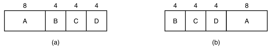
An example of shortest job first scheduling.
(a) Running four jobs in the original order.
(b) Running them in shortest job first order.
Here we find four jobs A, B, C, and D,
with run times of 8, 4, 4, and 4 minutes, respectively.
By running them in that order,
the turnaround time for A is 8 minutes,
for B is 12 minutes,
for C is 16 minutes, and
for D is 20 minutes,
for an average of 14 minutes.
Now let us consider running these four jobs using shortest job
first,
as shown in (b).
The turnaround times are now 4, 8, 12, and 20 minutes,
for an average of 11 minutes.
Shortest job first is provably optimal.
Consider the case of four jobs,
with run times of a, b, c, and d, respectively.
The first job finishes at time a,
the second finishes at time a + b, and so on.
The mean turnaround time is (4a + 3b + 2c + d)/4.
It is clear that job a contributes more to the average, than the other
times,
so it should be the shortest job, with b next, then c,
and finally d as the longest, as it affects only its own turnaround
time.
The same argument applies equally well to any number of jobs.
Shortest job first is only optimal,
when all the jobs are available simultaneously.
As a counterexample, consider five jobs, A through E,
with run times of 2, 4, 1, 1, and 1, respectively.
Their arrival times are 0, 0, 3, 3, and 3.
Initially, only A or B can be chosen,
since the other three jobs have not arrived yet.
Using shortest job first we will run the jobs in the order:
A, B, C, D, E, for an average wait of 4.6.
However, running them in the order B, C, D, E, A,
has an average wait of 4.4.
A preemptive version of shortest job first is shortest remaining time
next.
The scheduler always chooses the shortest process,
whose remaining run time is the shortest.
Again here, the run time has to be known in advance.
When a new job arrives,
its total time is compared to the current process’ remaining time.
If the new job needs less time to finish than the current process,
then the current process is suspended, and the new job started.
This scheme allows new short jobs to get good service.
From a certain perspective,
batch systems allow scheduling at three different levels,
as illustrated here:
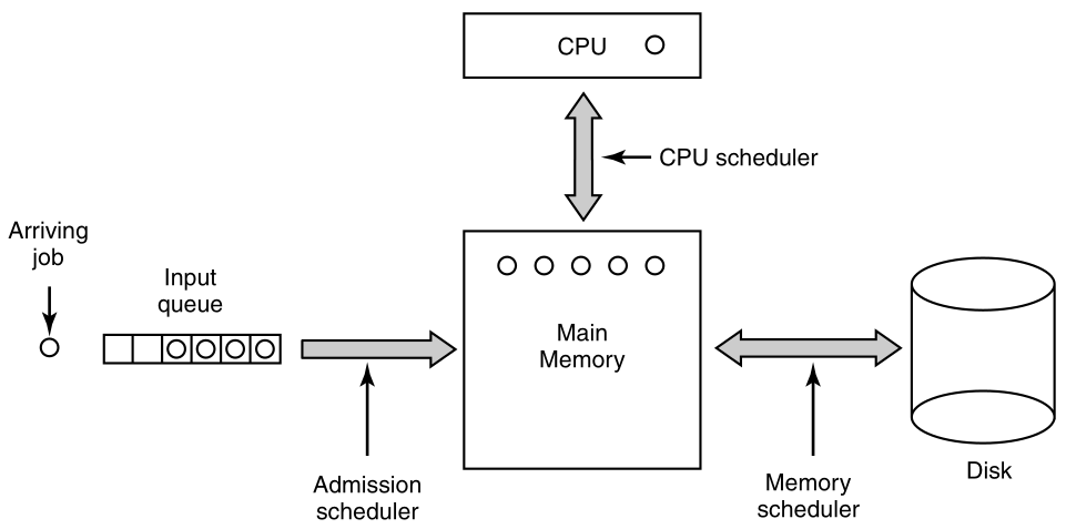
As jobs arrive at the system,
they are initially placed in an input queue stored on the disk.
The admission scheduler decides which jobs to admit to the system.
The others are kept in the input queue until they are selected.
A typical algorithm for admission control might be to look for a mix of
compute-bound jobs and I/O-bound jobs.
Alternatively, short jobs could be admitted quickly,
whereas longer jobs would have to wait.
The admission scheduler is free to hold some jobs in the input
queue,
and admit jobs that arrive later if it so chooses.
Once a job has been admitted to the system,
a process can be created for it,
and it can contend for the CPU.
However, it might well happen that the number of processes is so
large,
that there is not enough room for all of them in memory.
In that case, some of the processes have to be swapped out to
disk.
The second level of scheduling is,
deciding which processes should be kept in memory,
and which ones should be kept on disk.
We will call this scheduler the memory scheduler, since it determines
which processes are kept in memory and which on the disk.
This decision has to be reviewed frequently,
to allow the processes on disk to get some service.
However, since bringing a process in from disk is expensive,
the review probably should not happen more often than once per
second,
maybe less often.
If the contents of main memory are shuffled too often,
then a large amount of disk bandwidth will be wasted,
slowing down file I/O.
To optimize system performance as a whole,
the memory scheduler might well want to carefully decide,
how many processes it wants in memory,
called the degree of multiprogramming,
and what kind of processes.
If it has information about which processes are compute bound,
and which are I/O bound,
then it can try to keep a mix of these process types in memory.
As a very crude approximation,
if a certain class of process computes about 20% of the time,
then keeping five of them around is roughly the right number to keep the
CPU busy.
To make its decisions,
the memory scheduler periodically reviews each process on disk,
to decide whether or not to bring it into memory.
Among the criteria that it can use to make its decision, are the
following ones:
The third level of scheduling is actually picking,
from one of the ready processes in main memory to run next.
Often this is called the CPU scheduler,
and is the one people usually mean when they talk about the
scheduler.
Any suitable algorithm can be used here,
either preemptive or non-preemptive.
These include the ones described above,
as well as a number of algorithms to be described in the next
section.
We will now look at some algorithms that can be used in interactive
systems.
All of these can also be used as the CPU scheduler in batch systems as
well.
While three-level scheduling is not possible here,
two-level scheduling (memory scheduler and CPU scheduler) is possible
and common.
Below we will focus on the CPU scheduler, and some common scheduling
algorithms.
Now let us look at some specific scheduling algorithms.
One of the oldest, simplest, fairest,
and most widely used algorithms is round robin.
Each process is assigned a time interval, called its quantum,
which it is allowed to run.
If the process is still running at the end of the quantum,
then the CPU is preempted, and given to another process.
If the process has blocked, or finished before the quantum has
elapsed,
then the CPU switching is done when the process blocks, of course.
Round robin is easy to implement.
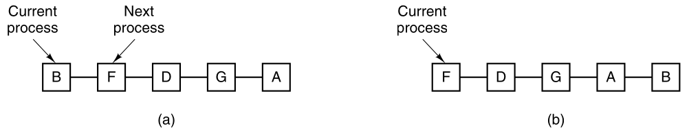
Round-robin scheduling.
(a) The list of runnable processes.
(b) The list of runnable processes after B uses up its quantum.
All the scheduler needs to do is maintain a list of runnable
processes,
as shown in (a).
When the process uses up its quantum,
it is put on the end of the list,
as shown in (b).
Switching overhead
The only interesting issue with round robin is the length of the
quantum.
Switching from one process to another,
requires a certain amount of time for doing the
administration-saving,
loading registers and memory maps, updating various tables and
lists,
flushing and reloading the memory cache, etc.
Suppose that this process switch or context switch, as it is sometimes
called,
takes 1 msec, including switching memory maps, flushing and reloading
the cache, etc.
Also suppose that the quantum is set at 4 msec.
With these parameters, after doing 4 msec of useful work,
the CPU will have to spend 1 msec on process switching.
Twenty percent of the CPU time will be wasted on administrative
overhead.
Clearly, this is too much.
To improve the CPU efficiency, we could set the quantum to, say, 100
msec.
Now the wasted time is only 1 percent.
But consider what happens on a time-sharing system,
if ten interactive users hit the carriage return key at roughly the same
time.
Ten processes will be put on the list of runnable processes.
If the CPU is idle, the first one will start immediately,
the second one may not start until 100 msec later, and so on.
The unlucky last one may have to wait 1 sec before getting a
chance,
assuming all the others use their full quanta.
Most users will perceive a 1-sec response to a short command as
sluggish.
Another factor is that if the quantum is set longer than the mean CPU
burst,
then preemption will rarely happen.
Instead, most processes will perform a blocking operation early,
before the quantum runs out, causing a process switch.
Eliminating preemption improves performance,
because process switches then only happen when they are logically
necessary,
that is, when a process blocks and cannot continue,
because it is logically waiting for something.
The conclusion can be formulated as follows:
setting the quantum too short causes too many process switches,
and lowers the CPU efficiency,
but setting it too long,
may cause poor response to short interactive requests.
A quantum of around 20-50 msec is often a reasonable compromise.
Round-robin scheduling makes the implicit assumption that:
all processes are equally important.
Frequently, the people who own and operate multi-user computers
disagree.
The need to take external factors into account leads to priority
scheduling.
The basic idea is straightforward:
Each process is assigned a priority,
and the runnable process with the highest priority is allowed to
run.
Even on a PC with a single owner,
there may be multiple processes,
some more important than others.
For example, a daemon process sending electronic mail in the
background,
should be assigned a lower priority than another,
perhaps a process displaying a video film on the screen in real
time.
To prevent high-priority processes from running indefinitely,
the scheduler may decrease the priority of the currently running
process,
at each clock tick (i.e., at each clock interrupt).
If this action causes its priority to drop,
below that of the next highest process,
then a process switch occurs.
Alternatively, each process may be assigned a maximum time
quantum,
a duration that it is allowed to run.
When this quantum is used up,
the next highest priority process is given a chance to run.
Priorities can be assigned to processes statically or
dynamically.
On a military computer, processes started by:
generals might begin at priority 100,
processes started by colonels at 90,
majors at 80, captains at 70, lieutenants at 60, and so on.
Alternatively, at a commercial computer center,
high-priority jobs might cost 100 dollars an hour,
medium priority 75 dollars an hour,
and low priority 50 dollars an hour.
The UNIX system has a command, nice,
which allows a user to voluntarily reduce the priority of his
process,
in order to be nice to the other users.
It is rarely used…
Priorities can also be assigned dynamically by the system,
to achieve certain system goals.
For example, some processes are highly I/O bound,
and spend most of their time waiting for I/O to complete.
Whenever such a process wants the CPU,,
it should be given the CPU immediately,
to let it start its next I/O request,
which can then proceed in parallel,
with another process actually computing.
Making the I/O-bound process wait a long time for the CPU,
will just mean having it around occupying memory,
for an unnecessarily long time.
A simple algorithm for giving good service to I/O-bound processes is
to:
set the priority to 1/f,
where f is the fraction of the last quantum that a process used.
A process that used only 1 msec of its 50 msec quantum would get
priority 50,
while a process that ran 25 msec before blocking would get priority
2,
and a process that used the whole quantum would get priority 1.
This is what we call a heuristic.
It is often convenient to group processes into priority
classes,
and use priority scheduling among the classes,
but round-robin scheduling within each class.
The image below shows a scheduling algorithm system with four priority
classes.
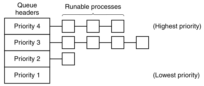
The scheduling algorithm is as follows:
as long as there are runnable processes in priority class 4,
just run each one for one quantum, round-robin fashion,
and never bother with lower priority classes.
If priority class 4 is empty,
then run the class 3 processes round robin.
If classes 4 and 3 are both empty,
then run class 2 round robin, and so on.
If priorities are not adjusted occasionally,
then lower priority classes may all starve to death.
MINIX3 uses a similar system to the image above,
although there are sixteen priority classes in the default
configuration.
In MINIX3, components of the operating system run as processes.
MINIX3 puts tasks (I/O drivers) and servers
(memory manager, file system, and network),
in the highest priority classes.
The initial priority of each task or service is defined at compile
time;
I/O from a slow device may be given lower priority,
when compared to I/O from a fast device, or even a server.
User processes generally have lower priority than system
components,
but all priorities can change during execution.
One of the earliest priority schedulers was in CTSS (Corbató et al.,
1962).
CTSS had the problem that process switching was very slow,
because the 7094 could hold only one process in memory.
Each switch meant swapping the current process to disk,
and reading in a new one from disk.
The CTSS designers quickly realized that it was more efficient to:
give CPU-bound processes a large quantum once in a while,
rather than giving them small quanta frequently (to reduce
swapping).
But, giving all processes a large quantum would mean poor response
time,
as we have already observed.
Their solution was to set up priority classes:
Processes in the first highest class were run for one quantum.
Processes in the next highest class were run for two quanta.
Processes in the next class were run for four quanta, and so on.
Whenever a process used up all the quanta allocated to it,
it was moved down one class.
As an example,
consider a process that needed to compute continuously for 100
quanta.
It would initially be given one quantum, then swapped out.
Next time it would get two quanta before being swapped out.
On succeeding runs it would get 4, 8, 16, 32, and 64 quanta,
although it would have used only 37 of the final 64 quanta to complete
its work.
Only 7 swaps would be needed (including the initial load),
instead of 100 with a pure round-robin algorithm.
Furthermore, as the process sank deeper and deeper into the priority
queues,
it would be run less and less frequently,
saving the CPU for short, interactive processes.
The following policy was adopted,
to prevent a process that needed to run for a long time when it first
started,
but became interactive later,
from being punished forever.
Whenever a carriage return was typed at a terminal,
the process belonging to that terminal was moved to the highest priority
class,
on the assumption that it was about to become interactive.
One fine day, some user with a heavily CPU-bound process discovered
that:
just sitting at the terminal and typing carriage returns,
at random every few seconds, did wonders for his response time.
He told all his friends.
Moral of the story:
getting it right in practice,
is much harder than getting it right in principle.
Many other algorithms have been used for assigning processes to
priority classes.
For example, the influential XDS 940 system (Lampson, 1968), built at
Berkeley,
had four priority classes, called terminal, I/O, short quantum, and long
quantum.
When a process that was waiting for terminal input was finally
awakened,
it went into the highest priority class (terminal).
When a process waiting for a disk block became ready,
it went into the second class.
When a process was still running when its quantum ran out,
it was initially placed in the third class.
However, if a process used up its quantum too many times in a row,
without blocking for terminal or other I/O,
then it was moved down to the bottom queue.
Many other systems use something similar,
to favor interactive users and processes,
over background ones.
For batch systems,
shortest job first always produces the minimum average response
time.
It would be nice if it could be used for interactive processes as
well.
To a certain extent, it can be.
Interactive processes generally follow the pattern of
wait for command, execute command, wait for command, execute command,
and so on.
If we regard the execution of each command as a separate “job”,
then we could minimize overall response time,
by running the shortest one first.
The only problem is:
figuring out which of the currently runnable processes is the shortest
one.
One approach is to make estimates based on past behavior,
and run the process with the shortest estimated running time.
Suppose that the estimated time-per-command for some terminal is
T0.
Now suppose its next run is measured to be T1.
We could update our estimate by taking a weighted sum of these two
numbers,
that is, aT0 + (1 − a)T1 .
Through the choice of the variable, a,
we can decide to have the estimation process forget old runs
quickly,
or remember them for a long time.
With a = 1/2, we get successive estimates of:
T0, T0/2 + T1/2,
T0/4 + T1/4 + T2/2,
T0/8 + T1/8 + T2/4 + T3/2
After three new runs,
the weight of T0 in the new estimate has dropped to 1/8.
The technique of estimating the next value in a series,
by taking the weighted average of:
the current measured value, and the previous estimate,
is sometimes called aging.
It is applicable to many situations,
where a prediction must be made, based on previous values.
Aging is especially easy to implement when a = 1/2.
All that is needed is:
to add the new value to the current estimate,
and divide the sum by 2 (by shifting it right 1 bit).
A completely different approach to scheduling is to:
make real promises to the users about performance,
and then live up to them.
One promise that is realistic to make and easy to live up to is
this:
If there are n users logged in while you are working,
then you will receive about 1/n of the CPU power.
Similarly, on a single-user system with n processes running,
all things being equal, each one should get 1/n of the CPU cycles.
To make good on this promise,
the system must keep track of:
how much CPU each process has had since its creation.
It then computes the amount of CPU each one is entitled to,
namely the time since creation divided by n.
Since the amount of CPU time each process has actually had is also
known,
it is straightforward to compute the ratio of:
actual CPU time consumed to CPU time entitled.
A ratio of 0.5 means that a process has only had half of what it should
have had,
and a ratio of 2.0 means that a process has had twice as much as it was
entitled to.
The algorithm is then to run the process with the lowest ratio,
until its ratio has moved above its closest competitor.
While making promises to the users, and then living up to them,
is a fine idea, it is difficult to implement.
However, another algorithm can be used to give similarly predictable
results,
with a much simpler implementation.
It is called lottery scheduling.
The basic idea is to:
give processes lottery tickets, for various system resources, such as
CPU time.
Whenever a scheduling decision has to be made,
a lottery ticket is chosen at random,
and the process holding that ticket, gets the resource.
When applied to CPU scheduling,
the system might hold a lottery 50 times a second,
with each winner getting 20 msec of CPU time as a prize.
To paraphrase George Orwell:
“All processes are equal,
but some processes are more equal.”
More important processes can be given extra tickets,
to increase their odds of winning.
If there are 100 tickets outstanding,
and one process holds 20 of them,
then it will have a 20 percent chance of winning each lottery.
In the long run, it will get about 20 percent of the CPU.
In contrast to a priority scheduler,
where it is very hard to state what having a priority of 40 actually
means,
here the rule is clear:
a process holding a fraction, f, of the tickets,
will get about a fraction, f, of the resource in question.
Lottery scheduling has several interesting properties:
Responsiveness
For example, if a new process shows up, and is granted some
tickets,
at the very next lottery, it will have a chance of winning,
in proportion to the number of tickets it holds.
In other words, lottery scheduling is highly responsive.
Exchangeability
Cooperating processes may exchange tickets if they wish.
For example, when a client process sends a message to a server
process,
and then blocks, it may give all of its tickets to the server,
to increase the chance of the server running next.
When the server is finished,
it returns the tickets, so the client can run again.
In fact, in the absence of clients,
servers need no tickets at all.
Lottery scheduling can be used to solve hard problems,
that are difficult to handle with other methods.
One example is a video server,
in which several processes are feeding video streams to their
clients,
but at different frame rates.
Suppose that the processes need frames at 10, 20, and 25
frames/sec.
By allocating these processes 10, 20, and 25 tickets,
respectively,
they will automatically divide the CPU,
in approximately the correct proportion, that is:
10 : 20 : 25.
So far we have assumed that each process is scheduled on its
own,
without regard to who its owner is.
As a result, if user 1 starts up 9 processes,
and user 2 starts up 1 process,
with round robin or equal priorities,
user 1 will get 90% of the CPU,
and user 2 will get only 10% of it.
To prevent this situation,
some systems take into account who owns a process,
before scheduling it.
In this model, each user is allocated some fraction of the CPU,
and the scheduler picks processes,
in such a way as to enforce it.
Thus if two users have each been promised 50% of the CPU,
they will each get that,
no matter how many processes they have in existence.
As an example, consider a system with two users,
each of which has been promised 50% of the CPU.
User 1 has four processes, A, B, C, and D,
and user 2 has only 1 process, E.
If round-robin scheduling is used,
then a possible scheduling sequence that meets all the constraints, is
this one:
A E B E C E D E A E B E C E D E …
On the other hand, if user 1 is entitled to twice as much CPU time as
user 2,
then we might get:
A B E C D E A B E C D E …
Numerous other possibilities exist, of course,
and can be exploited, depending on what the notion of fairness is.
A real-time system is one in which time plays an essential
role.
Typically, one or more physical devices external to the computer
generate stimuli,
and the computer must react appropriately to them within a fixed amount
of time.
For example, the computer behind a compact disc player receives
bits,
as they come off the drive, and must convert them into music,
within a very tight time interval.
If the calculation takes too long,
then the music will sound peculiar.
Other real-time systems are patient monitoring in a hospital
intensive-care unit,
the autopilot in an aircraft, and
robot control in an automated factory.
In all these cases, having the right answer, but having it too
late,
is often just as bad as not having it at all.
Real-time systems are generally categorized as hard real time,
meaning there are absolute deadlines that must be met, or else, and soft
real time, meaning that missing an occasional deadline is undesirable,
but nevertheless tolerable.
In both cases, real-time behavior is achieved by dividing the program
into a number of processes, each of whose behavior is predictable and
known in advance.
These processes are generally short lived and can run to completion in
well under a second.
When an external event is detected, it is the job of the scheduler to
schedule the processes in such a way that all deadlines are met.
The events that a real-time system may have to respond to,
can be further categorized as:
periodic (occurring at regular intervals) or
aperiodic (occurring unpredictably).
A system may have to respond to multiple periodic event
streams.
Depending on how much time each event requires for processing,
it may not even be possible to handle them all.
For example, if there are m periodic events,
and event i occurs with period Pi,
and requires Ci seconds of CPU time to handle each event,
then the load can only be handled if
\(\sum_{i=1}^{m} \frac{C_i}{P_i} \leq 1\)
A real-time system that meets this criteria, is said to be schedulable.
As another example, consider a soft real-time system with three
periodic events,
with periods of 100, 200, and 500 msec, respectively.
If these events require 50, 30, and 100 msec of CPU time per event,
respectively,
then the system is schedulable,
because 0.5 + 0.15 + 0.2 < 1.
If a fourth event with a period of 1 sec is added,
then the system will remain schedulable,
as long as this event does not need more than 150 msec of CPU time per
event.
Implicit in this calculation, is the assumption that:
the context-switching overhead is so small, that it can be ignored.
Real-time scheduling algorithms can be static or dynamic.
Static make their scheduling decisions before the system starts
running.
Static scheduling only works when:
there is perfect information available in advance,
about the work needed to be done,
and the deadlines that have to be met.
Dynamic make their scheduling decisions at run time.
Dynamic scheduling algorithms do not have these restrictions.
Up until now, we have tacitly assumed that:
all the processes in the system belong to different users,
and are thus competing for the CPU.
While this is often true,
sometimes it happens that one process has many children,
all running under its control.
For example, a database management system process may have many
children.
Each child might be working on a different request,
or each one might have some specific function to perform
(query parsing, disk access, etc.).
The main process may han an idea of which of its children are the most
important
(or the most time critical), and which the least.
Unfortunately, none of the schedulers discussed above,
accept any input from user processes, about scheduling decisions.
As a result, the scheduler rarely makes the best choice.
The solution to this problem is to separate the scheduling
mechanism,
from the scheduling policy.
What this means is that:
The scheduling algorithm is parameterized in some way,
but the parameters can be filled in by user processes.
Let us consider the database example once again.
Suppose that the kernel uses a priority scheduling algorithm,
but provides a system call,
by which a process can set (and change) the priorities of its
children.
In this way, the parent can control in detail, how its children are
scheduled,
even though it does not do the scheduling itself.
Here the mechanism is in the kernel,
but policy is set by a user process.
When several processes each have multiple threads,
we have two levels of parallelism present:
processes and threads.
Scheduling in such systems differs substantially,
depending on whether user-level threads,
or kernel-level threads (or both) are supported.
Let us consider user-level threads first.
Since the kernel is not aware of the existence of threads,
it operates as it always does, picking a process, say, A,
and giving A control for its quantum.
The thread scheduler inside A, decides which thread to run, say
A1.
Since there are no clock interrupts to multiprogram threads,
this thread may continue running, as long as it wants to.
If it uses up the process’ entire quantum,
then the kernel will select another process to run.
When the process A finally runs again, thread A1 will resume
running.
It will continue to consume all of A’s time, until it is finished.
However, its antisocial behavior will not affect other processes.
They will get whatever the scheduler considers their appropriate
share,
no matter what is going on inside process A.
Now consider the case that:
A’s threads have relatively little work to do, per CPU burst,
for example, 5 msec of work within a 50-msec quantum.
Consequently, each one runs for a little while,
then yields the CPU back, to the thread scheduler.
This might lead to the sequence:
A1, A2, A3, A1, A2, A3, A1, A2, A3, A1
before the kernel switches to process B.
This situation is illustrated in (a).
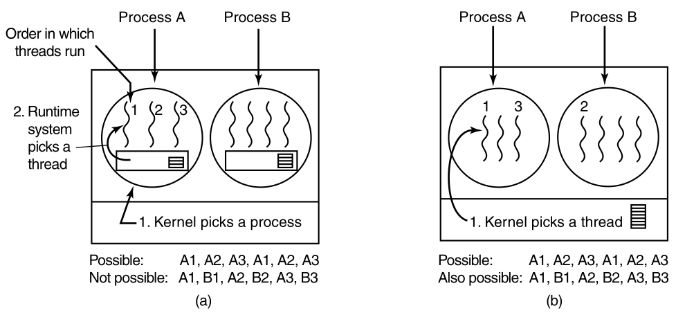
(a) Possible scheduling of user-level threads,
with a 50-msec process quantum,
and threads that run 5 msec per CPU burst.
The scheduling algorithm used by the run-time system,
can be any of the ones described above.
In practice, round-robin scheduling and priority scheduling are most
common.
The only constraint is:
the absence of a clock to interrupt a thread, that has run too long.
Now consider the situation with kernel-level threads.
Here the kernel picks a particular thread to run.
It does not have to take into account which process the thread belongs
to,
but it can if it wants to.
The thread is given a quantum,
and if it exceeds the quantum,
then it is forceably suspended.
With a 50-msec quantum, but threads that block after 5 msec,
the thread order for some period of 30 msec might be:
A1, B1, A2, B2, A3, B3,
something not possible with these parameters, and user-level
threads.
This situation is partially depicted in (b) above.
A major difference between user-level threads and kernel-level
threads,
is the performance:
Doing a thread switch with user-level threads,
takes a handful of machine instructions.
With kernel-level threads,
it requires a full context switch,
changing the memory map,
and invalidating the cache,
which is several orders of magnitude slower.
On the other hand, with kernel-level threads,
having a thread block on I/O,
does not suspend the entire process,
as it does with user-level threads.
Since the kernel knows that switching from:
a thread in process A to a thread in process B,
is more expensive than running a second thread in process A
(due to having to change the memory map and having the memory cache
spoiled),
it can take this information into account, when making a decision.
For example, given two threads that are otherwise equally
important,
with one of them belonging to the same process as a thread that just
blocked,
and one belonging to a different process,
preference could be given to the former.
Another important factor to consider is that:
user-level threads can employ an application-specific thread
scheduler.
For example, consider a web server, which has a dispatcher thread,
to accept and distribute incoming requests, to worker threads.
Suppose that a worker thread has just blocked,
and the dispatcher thread and two worker threads, are ready.
Who should run next?
The run-time system, knowing what all the threads do,
can easily pick the dispatcher to run next,
so it can start another worker running.
This strategy maximizes the amount of parallelism,
in an environment where workers frequently block on disk I/O.
With kernel-level threads,
the kernel would never know what each thread did
(although they could be assigned different priorities).
However, application-specific thread schedulers can tune an application
better,
compared to how the kernel can.
Having completed our study of the principles of:
process management, interprocess communication, and scheduling,
we can now take a look at how they are applied in MINIX3.
Unlike UNIX, whose kernel is a monolithic program not split up into
modules,
MINIX3 itself is a collection of processes,
that communicate with each other and also with user processes,
using a single interprocess communication primitive,
message passing.
This design gives a more modular and flexible structure,
making it easy, for example,
to replace the entire file system by a completely different one,
without having even to recompile the kernel.
Let us begin our study of MINIX3 by taking a bird’s-eye view of the
system.
MINIX3 is structured in four layers,
with each layer performing a well-defined function.
The four layers are illustrated here:
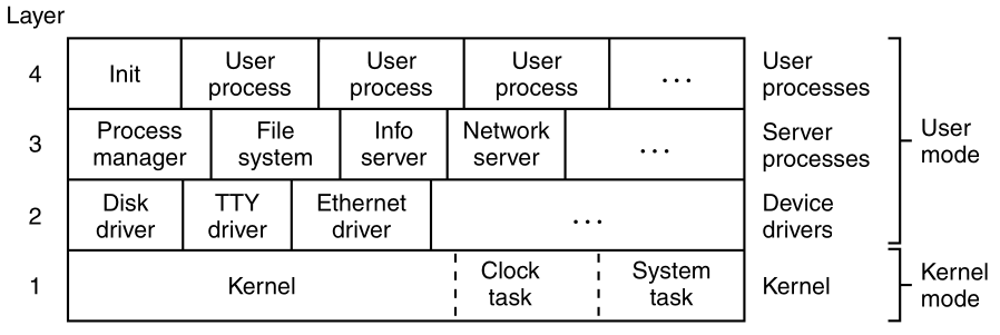
MINIX3 is structured in four layers.
Only processes in the bottom layer may use privileged (kernel mode) instructions.
The kernel in the bottom layer schedules processes,
and manages the transitions between the ready, running, and blocked
states.
The kernel also handles all messages between processes.
Message handling requires checking for legal destinations,
locating the send and receive buffers in physical memory,
and copying bytes from sender to receiver.
Also part of the kernel, is support for access to I/O ports and
interrupts,
which on modern processors, require use of privileged kernel mode
instructions,
not available to ordinary processes.
In addition to the kernel itself,
this layer contains two more modules,
that function similarly to device drivers.
The clock task is an I/O device driver,
in the sense that it interacts with the hardware that generates timing
signals.
But, it is not user-accessible, like a disk or communications line
driver.
It interfaces only with the kernel.
One of the main functions of layer 1,
is to provide a set of privileged kernel calls,
to the drivers and servers above it.
These include reading and writing I/O ports,
copying data between address spaces, etc.
Implementation of these calls is done by the system task.
Although the system task and the clock task are compiled into the
kernel’s address space,
they are scheduled as separate processes and have their own call
stacks.
Most of the kernel and all of the clock and system tasks are written
in C.
However, a small amount of the kernel is written in assembly
language.
The assembly language parts deal with interrupt handling,
the low-level mechanics of managing context switches between
processes
(saving and restoring registers and the like),
and low-level parts of manipulating the MMU hardware.
Mostly, the assembly-language code handles only some parts of the kernel
function,
those that deal directly with the hardware, at a very low level,
and which cannot be expressed in C.
When MINIX3 is ported to a new architecture,
these parts have to be rewritten.
The three layers above the kernel could be considered to be a single
layer,
because the kernel fundamentally treats them all of them the same
way.
Each one is limited to user mode instructions,
and each is scheduled to run by the kernel.
None of them can access I/O ports directly.
None of them can access memory outside the segments allotted to it.
However, processes potentially have special privileges
(such as the ability to make kernel calls).
This is the difference between processes in layers 2, 3, and 4.
The processes in layer 2 have the most privileges,
those in layer 3 have some privileges,
and those in layer 4 have no special privileges.
Processes in layer 2, called device drivers,
are allowed to request that the system task read data from,
or write data to, I/O ports on their behalf.
A driver is needed for each device type, including:
disks, printers, terminals, and network interfaces.
If other I/O devices are present,
then a driver is needed for each one of those, as well.
Device drivers may also make other kernel calls,
such as requesting that newly read data be copied,
to the address space of a different process.
As we noted before, operating systems do two things:
first, manage resources, and
second, provide an extended machine, by implementing system calls.
In MINIX3, the resource management is largely done by the drivers in
layer 2,
with help from the kernel layer,
when privileged access to I/O ports, or the interrupt system, is
required.
A note about the terms “task” and “device driver” is needed.
In older versions of MINIX,
all device drivers were compiled together with the kernel,
which gave them access to:
data structures belonging to the kernel, and each other.
They also could all access I/O ports directly.
They were referred to as “tasks”,
to distinguish them from pure independent user-space processes.
In MINIX3, device drivers have been implemented completely in
user-space.
The only exception is the clock task,
which is arguably not a device driver, in the same sense as
drivers,
that can be accessed through device files, by user processes.
We will try to use term “task”,
only when referring to the clock task or the system task,
both of which are compiled into the kernel to function.
We have been careful to replace the word “task” with “device
driver”,
where we refer to user-space device drivers.
In MINIX3 source code,
function names, variable names, and comments,
have not been as carefully updated.
Thus, as you look at source code during your study of MINIX3,
you may find the word “task” where “device driver” is meant.
The third layer contains servers,
processes that provide useful services to the user processes.
Two servers are essential:
First, the process manager (PM) carries out:
all the MINIX3 system calls that involve starting or stopping process
execution,
such as: fork, exec, and
exit,
as well as system calls related to signals,
such as: alarm and kill,
which can alter the execution state of a process.
The process manager also is responsible for managing memory,
for example, with the brk system call.
Second, the file system (FS) carries out all the file system
calls,
such as read, mount, and
chdir.
The file system has been carefully designed as a file “server”,
and could be moved to a remote machine, with few changes.
It is important to understand the difference between kernel calls and POSIX system calls.
Kernel calls are low-level functions provided by the system
task,
to allow the drivers and servers to do their work.
Reading a hardware I/O port is a typical kernel call.
In contrast, the POSIX system calls such as read, fork, and
unlink,
are high-level calls, defined by the POSIX standard,
and are available to user programs in layer 4.
User programs contain many POSIX calls, but no kernel calls.
Occasionally when we are not being careful with our language,
we may call a kernel call a system call.
The mechanisms used to make these calls are similar,
though kernel calls can be considered a special subset of system
calls.
In addition to the PM and FS, other servers exist in layer 3.
They perform functions that are specific to MINIX3.
It is safe to say that:
the functionality of both the process manager, and the file
system,
will be found in any operating system.
System call interpretation is done by the process manager, and file
system servers,
both of which are in in layer 3.
The information server (IS) handles jobs such as:
providing debugging and status information about other drivers and
servers,
something that is more necessary in a system like MINIX3,
designed for experimentation,
than would be the case for a commercial operating system,
which users cannot alter.
The reincarnation server (RS) starts, and if necessary
restarts,
device drivers that are not loaded into memory at the same time as the
kernel.
In particular, if a driver fails during operation,
then the reincarnation server detects this failure,
kills the driver, if it is not already dead,
and starts a fresh copy of the driver.
This improves fault tolerance.
This functionality is absent from most operating systems.
On a networked system, the optional network server (inet) is also in
level 3.
Servers cannot do I/O directly,
but they can communicate with drivers to request I/O.
Servers can also communicate with the kernel, via the system task.
The system does not need to be recompiled,
to include additional servers.
The process manager and the file system can be supplemented,
with the network server, and other servers,
by attaching additional servers, as required,
when MINIX3 starts up or later.
Device drivers, although typically started when the system is
started,
can also be started later.
Both device drivers and servers are compiled,
and stored on disk as ordinary executable files,
but when properly started up,
they are granted access to the special privileges needed.
A user program, called service,
provides an interface to the reincarnation server, which manages
this.
Although the drivers and servers are independent processes,
they differ from user processes,
in that normally they never terminate, while the system is active.
We will refer to drivers and servers in layers 2 and 3 as system
processes.
Arguably, system processes are part of the operating system.
They do not belong to any user,
and many, if not all of them,
will be activated before the first user logs on.
Another difference between system processes and user processes,
is that system processes have higher execution priority than user
processes.
Further, normally drivers have higher execution priority than
servers,
but this is not automatic.
Execution priority is assigned on a case-by-case basis in MINIX3;
it is possible for a driver that services a slow device,
may be given lower priority than a server, that must respond
quickly.
Finally, layer 4 contains all the user:
processes-shells, editors, compilers, and user-written
a.out programs.
Many user processes come and go,
as users log in, do work, and log out.
A running system normally has some user processes,
that are started when the system is booted,
and which run forever.
One of these is init, which we will describe in the next
section.
Also, several daemons are likely to be running.
A daemon is a background process that executes periodically,
or always waits for some event,
such as the arrival of a packet from the network.
In a sense, a daemon is a server,
that is started independently, and runs as a user process.
Like true servers installed at startup time,
it is possible to configure a daemon,
to have a higher priority than ordinary user processes.
Processes in MINIX3 follow the previous process model above.
Processes can create subprocesses,
which in turn can create more subprocesses,
yielding a tree of processes.
All the user processes in the whole system,
are part of a single tree with init at the root.
Recall the last figure above.
Servers and drivers are a special case, of course,
since some of them must be started before any user process,
including init.
How does an operating system start up?
We will summarize the MINIX3 startup sequence now:
On most computers with disk devices, there is a boot disk
hierarchy.
Typically, if an external disk is inserted, it will be the boot
disk.
If no external disk is present, and a CD-ROM is present,
then it becomes the boot disk.
If there is neither a disk nor a CD-ROM present,
then the first hard drive becomes the boot disk.
The order of this hierarchy may be configurable,
by entering the BIOS,
immediately after powering the computer up.
Additional devices, network devices, and other removable storage
devices,
may be supported as well.
When the computer is turned on,
if the boot device is a floppy diskette,
then the hardware reads the first sector, of the first track, of the
boot disk,
into memory, and executes the code it finds there.
On a diskette, this sector contains the bootstrap
program.
It is very small, since it has to fit in one sector (512 bytes).
The MINIX3 bootstrap loads a larger program,
boot,
which then loads the operating system itself.
In contrast, hard disks require an intermediate step.
A hard disk is divided into partitions,
and the first sector of a hard disk contains a small program,
and the disk’s partition table.
Collectively these two pieces are called the master boot record
(MBR).
The program part is executed, to read the partition table,
and to select the active partition.
The active partition has a bootstrap on its first
sector,
which is then loaded and executed,
to find and start a copy of boot in the partition,
exactly as is done when booting from a diskette.
CD-ROMs came along later in the history of computers,
compared to floppy disks and hard disks,
and when support for booting from a CD-ROM is present,
it is capable of more than just loading one sector.
A computer that supports booting from a CD-ROM,
can load a large block of data into memory immediately.
Typically what is loaded from the CD-ROM is an exact copy of a bootable
floppy disk,
which is placed in memory, and used as a RAM disk.
After this first step, control is transferred to the RAM disk,
and booting continues, exactly as if a physical floppy disk were the
boot device.
On an older computer, which has a CD-ROM drive,
but does not support booting from a CD-ROM,
the bootable floppy disk image can be copied to a floppy disk,
which can then be used to start the system.
The CD-ROM must be in the CD-ROM drive, of course,
since the bootable floppy disk image expects that.
Then, on the diskette or partition,
the MINIX3 boot program looks for a specific multipart
file,
and loads the individual parts into memory, at the proper
locations.
This is the boot image.
All parts of the boot image are separate programs.
Kernel
The most important parts are the kernel
(which include the clock task and the system task),
the process manager, and the file system.
After the essential kernel, process manager, and file system,
have all been loaded, many other parts could be loaded separately.
Drivers and servers
At least one disk driver, and several other programs are loaded in the
boot image.
These include the:
reincarnation server, the RAM disk, console, and log drivers, and
init.
The reincarnation server must be part of the boot image.
It gives ordinary processes, loaded after initialization,
the special priorities and privileges,
which make them into system processes.
It can also restart a crashed driver, which explains its name.
Disk driver
As mentioned above, at least one disk driver is essential.
If the root file system is to be copied to a RAM disk,
then the memory driver is also required,
otherwise it could be loaded later.
tty and logging
The tty and log drivers are optional in the boot
image.
They are loaded early,
just because it is useful to be able to display messages on the
console,
and save information to a log, early in the startup process.
Kernel
Startup takes many steps.
Operations that are in the realms of the disk driver and the file
system,
must be performed by boot, before these parts of the system are
active.
In a later section, we will fully detail how MINIX3 is started.
For now, once the those loading operation are complete,
then the kernel starts running.
During its initialization phase,
the kernel starts the system and clock tasks,
and then the process manager and the file system.
The process manager and the file system then cooperate,
in starting other servers and drivers,
that are part of the boot image.
When all these have run and initialized themselves,
they will block, waiting for something to do.
MINIX3 scheduling prioritizes processes.
init
Only when all tasks, drivers, and servers loaded in the boot image have
blocked,
will init, the first user process, be executed.
init could certainly be loaded later,
but it controls initial configuration of the system,
and so it was easiest just to include it in the boot image file.
System components loaded with the boot image,
or during initialization, are shown below:
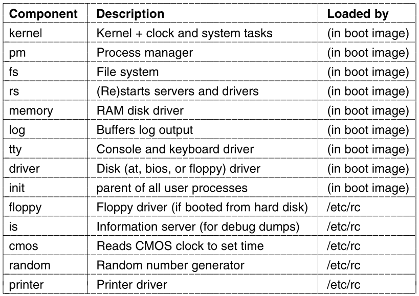
Others such as an Ethernet driver and the inet server may also be
present.
init is the first user process,
and also the last process loaded,
as part of the boot image.
You might think building of a process tree begins once init
starts running.
Well, not exactly.
That would be true in a conventional operating system,
but MINIX3 is different.
First, there are already quite a few system processes running,
by the time init gets to run.
The tasks CLOCK and SYSTEM, that run within
the kernel,
are unique processes, that are not visible outside of the kernel.
They receive no PIDs, and are not considered part of any tree of
processes.
The process manager is the first process to run in user space;
it is given PID 0,
and is neither a child, nor a parent, of any other process.
The reincarnation server is made the parent of all the other
processes,
which are started from the boot image (e.g., the drivers and
servers).
The logic of this, is that the reincarnation server is the process that
should be informed,
if any of these should need to be restarted.
init has PID
1As we will see, even after init starts running,
there are differences between the way a process tree is built in
MINIX3,
and the conventional concept.
init in a UNIX-like system is given PID 1,
and even though init is not the first process to run,
the traditional PID 1 is reserved for it in MINIX3.
Like all the user space processes in the boot image
(except the process manager),
init is made one of the children of the reincarnation
server, rs.
/etc/rc
starts init’s childrenAs in a standard UNIX-like system,
init first executes the /etc/rc shell
script.
This script starts additional drivers and servers,
that are not part of the boot image.
Any program started by the rc script will be a child of
init.
One of the first programs run is a utility called
service.
service itself runs as a child of init, as
would be expected.
But now things once again vary from the conventional.
service is the user interface to the reincarnation
server.
The reincarnation server can start an ordinary program,
and converts it into a system process.
It starts:
floppy (if it was not used in booting the system),
cmos (which is needed for rc to initialize and
read the real-time clock), and
is, the information server,
which manages the debug dumps,
that are produced by pressing function keys (F1, F2, etc.),
on the console keyboard.
One of the actions of the reincarnation server is to adopt all system
processes,
except the process manager, as its own children.
Up to this point all files needed must be found on the root device
/.
Next, programs in other directories are started.
The servers and drivers needed initially are in the
/sbin directory;
other commands needed for startup are in /bin.
Once the initial startup steps have been completed,
other file systems such as /usr are mounted.
rc startup script
An important function of the startup rc script is to check
for filesystem problems,
that might have resulted from a previous system crash.
The test is simple:
When the system is shutdown correctly, by executing the shutdown
command,
an entry is written to the login history file,
/usr/adm/wtmp.
The command shutdown –C
checks whether the last entry in wtmp is a shutdown
entry.
If not, it is assumed an abnormal shutdown occurred,
and the fsck utility is run to check all file systems.
The final job of /etc/rc is to start daemons.
This may be done by subsidiary scripts.
If you look at the output of a ps axl command,
which shows both PIDs and parent PIDs (PPIDs),
then you will see that daemons, such as update and
usyslogd,
will normally be the among the first persistent processes,
which are children of init.
Finally init reads the file
/etc/ttytab,
which lists all potential terminal devices.
Those devices that can be used as login terminals
have an entry in the getty field of /etc/ttytab,
and init forks off a child process for each such
terminal.
In the standard distribution, those devices include:
just the main console, and up to three virtual consoles,
but serial lines and network pseudo terminals can be added.
Normally, each child executes /usr/bin/getty which prints a
message,
then waits for a name to be typed.
If a particular terminal requires special treatment (e.g., a dial-up
line),
then /etc/ttytab can specify a command, such as
/usr/bin/stty,
to be executed, to initialize the line, before running getty.
When a user types a name to log in, the binary
/usr/bin/login is called, with the username as its
argument.
login determines if a password is required,
and if so, prompts for, and verifies the password.
After a successful login, login executes the user’s
shell
The default shell is /bin/sh,
but another shell may be specified in the /etc/passwd
file.
The shell waits for commands to be typed,
and then forks off a new process for each command.
The shells are the children of init,
the user processes are the grandchildren of init,
and all the user processes in the system are part of a single tree.
Except for the tasks compiled into the kernel and the process
manager,
all processes, both system processes and user processes, form a
tree.
But unlike the process tree of a conventional UNIX system,
init is not at the root of the entire OS tree,
and the structure of the tree does not allow one to determine the
startup order,
the order in which system processes were started.
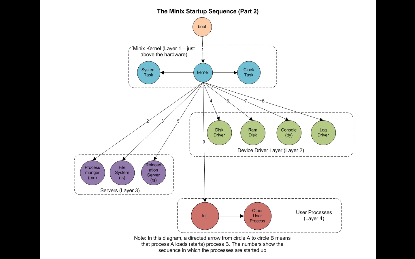
Note: this is the startup sequence,
not the process tree, which is artificially re-architected during
boot!
The two principal MINIX3 system calls for process management
are:
fork and exec.
fork is the only way to create a new process.
Exec allows a process to execute a specified program.
When a program is executed, it is allocated a portion of memory,
whose size is specified in the program file’s header.
It keeps this amount of memory throughout its execution,
although the distribution among data segment, stack segment, and
unused,
can vary as the process runs.
All the information about a process is kept in the process
table,
which is divided up among the kernel, process manager, and file
system,
with each one having those fields that it needs.
When a new process comes into existence (by fork),
or an old process terminates (by exit or a signal),
the process manager first updates its part of the process table,
and then sends messages to the file system and kernel,
telling them to do likewise.
++++++++++++++++++ Cahoot-02-8
Three primitives are provided for sending and receiving
messages.
They are called by the C library procedures.
send(dest, &message);
to send a message to process destination.
receive(source, &message);
to receive a message from process source (or ANY), and
sendrec(src_dst, &message);
to send a message, and wait for a reply from the same process.
The second parameter in each call, message,
is the local address of the message data.
The message passing mechanism in the kernel,
copies the message from the sender to the receiver.
The reply (for sendrec) overwrites the original message.
In principle, this kernel mechanism could be replaced,
by a function which copies messages over a network,
to a corresponding function on another machine,
to implement a distributed system.
In practice, this would be complicated somewhat,
since message contents can include pointers to large data
structures,
and a distributed system would need to copy data itself over the
network.
Each task, driver or server process,
is allowed to exchange messages only with certain other processes.
Details of how this is enforced will be described later.
In the layers illustrated previously,
the usual flow of messages is downward.
For example,
user processes in layer 4, can initiate messages to servers in layer
3,
servers in layer 3, can initiate messages to drivers in layer 2.
Also, messages can be sent between processes in the same system
layer,
or between processes in adjacent system layers.
User processes cannot send messages to each other.
When a process sends a message to a process,
but that is not currently waiting for a message,
the sender blocks, until the destination does a receive.
In other words, MINIX3 uses the rendezvous method,
to avoid the problems of buffering sent, but not yet received,
messages.
The advantage of this approach is that:
it is simple, and eliminates the need for buffer management
(including the possibility of running out of buffers).
In addition, because all messages are of fixed length, determined at
compile time,
buffer overrun errors caused by messages are structurally prevented.
There are restrictions on exchanges of messages.
if process A is allowed to generate a send or
sendrec, directed to process B,
then process B can be allowed to call receive with A
designated as the sender,
but B should not be allowed to send to A.
If A tries to send to B, and then blocks,
and B tries to send to A, and then blocks,
then we have a deadlock.
The “resource” that each would need to complete the operations,
is not a physical resource like an I/O device,
but is a call to receive by the other process,
the target of the message.
We will have more to say about deadlocks later.
Occasionally something different from a blocking message is
needed.
There exists another important message-passing primitive.
It is called by the C library procedure
notify(dest);
This used when a process needs to notify another process,
that something important has happened.
A notify is non-blocking, which means the sender continues
to execute,
whether or not the recipient is waiting.
Because it does not block,
a notify avoids the possibility of a message deadlock.
The message mechanism is used to deliver a notification,
but the information conveyed is limited.
In the general case, the message contains only:
the identity of the sender, and
a timestamp added by the kernel.
Sometimes this is all that is necessary.
For example, when one of the function keys (F1-12) is pressed
the keyboard uses a notify call.
In MINIX3, function keys are used to trigger debugging dumps.
The Ethernet driver is an example,
a process that generates only one kind of debug dump,
and never needs to get any other communication from the console
driver.
Thus a notification to the Ethernet driver, from the keyboard
driver,
when the dump-Ethernet-stats key is pressed, is unambiguous.
In other cases, a notification is not sufficient,
but upon receiving a notification,
the target process can send a message to the originator of the
notification,
to request more information.
There is a reason notification messages are so simple (small).
A notify call does not block, and so it can be made any
tim,
even when the recipient has not yet executed a
receive.
A notification that cannot be received, is easily stored,
so that the next time the recipient calls receive.
the recipient can be informed of it.
In fact, a single bit suffices.
Notifications are meant for use between system processes,
of which there can be only a relatively small number.
Every system process has a bitmap for pending notifications,
with a distinct bit for every system process.
So if process A needs to send a notification to process B,
at a time when process B is not blocked on a receive,
then the message-passing mechanism sets a bit,
which corresponds to A in B’s bitmap of pending notifications.
When B finally does a receive,
the first step is to check its pending notifications bitmap.
It can learn of attempted notifications from multiple sources this
way.
The single bit is enough to regenerate the information content of the
notification.
It tells the identity of the sender,
and the message passing code in the kernel adds the timestamp,
at which it is delivered.
Timestamps are used primarily to see if timers have expired,
so it does not matter that the timestamp may be for a different
time,
later than the time when the sender first tried to send the
notification.
There is a further refinement to the notification mechanism.
In certain cases, an additional field of the notification message is
used:
When the notification is generated to inform a recipient of an
interrupt,
a bitmap of all possible sources of interrupts is included in the
message.
When the notification is from the system task,
a bitmap of all pending signals for the recipient is part of the
message.
The natural question at this point is:
How can this additional information be stored,
when the notification must be sent to a unexpectant process,
that is not trying to receive a message?
The answer is that:
these bitmaps are in kernel data structures.
They do not need to be copied to be preserved.
If a notification must be deferred, and reduced to setting a single
bit,
then when the recipient eventually does a receive,
the notification message can be regenerated,
knowing the origin of the notification,
to specify which additional information needs to be included in the
message.
And for the recipient,
the origin of notification itself,
specifies whether the message contains additional information,
and, if so, how it is to be interpreted.
A few other primitives related to interprocess communication
exist.
They will be mentioned in a later section.
They are less important than send, receive,
sendrec, and notify.
++++++++++++++++++ Cahoot-02-9
The interrupt system is what keeps a multiprogramming operating system going.
Processes block when they make requests for input,
allowing other processes to execute.
When input becomes available,
an unrelated current running process may be interrupted,
by the disk, keyboard, or other hardware.
The clock also generates interrupts,
that are used to make sure a running user process that has not requested
input,
eventually relinquishes the CPU, to give other processes their chance to
run.
It is the job of the lowest layer of MINIX3,
to hide these interrupts, by turning them into messages.
As far as processes are concerned,
when an I/O device completes an operation,
it sends a message to some process,
waking it up and making it eligible to run.
Interrupts are also generated by software,
in which case they are often called traps.
The send and receive operations that we
described above,
are translated by the system library, into software interrupt
instructions,
which have exactly the same effect as hardware-generated
interrupts.
The process that executes a software interrupt is immediately
blocked,
and the kernel is activated, to process the interrupt.
User programs do not refer to send or receive
directly.
For any system call we reviewed before
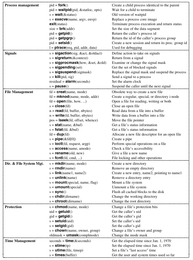
is called, either directly or by a library routine,
sendrec is used internally, and a software interrupt is
generated.
Each time a process is interrupted
(whether by a conventional I/O device, or by the clock)
or due to execution of a software interrupt instruction,
there is an opportunity to re-evaluate,
determining which process is most deserving of an opportunity to
run.
This must also be done whenever a process terminates,
but in a system like MINIX3,
interruptions due to I/O operations, the clock, or message
passing,
occur more frequently than process termination.
The MINIX3 scheduler uses a multilevel queueing system.
Sixteen queue priorities are defined,
although recompiling to use more or fewer queues is easy.
The lowest priority queue is used only by the IDLE process,
which runs when there is nothing else to do.
User processes start,
they default to a queue level several higher than the lowest.
Servers are normally scheduled in queues,
with priorities higher than allowed for user processes,
Further, drivers are put in queues with priorities higher than those of servers,
Next, the clock and system tasks are scheduled in the highest priority queue.
Not all of the sixteen available queues, are likely to be in use at
any time.
Processes are started in only a few of them.
A process may be moved to a different priority queue by the
system,
or (within certain limits) by a user who invokes the nice
command.
The extra levels are available for experimentation,
and as additional drivers are added to MINIX3,
the default settings can be adjusted for best performance.
For example, if it were desired to add a server,
to stream digital audio or video to a network,
such a server might be assigned a higher starting priority than current
servers,
or the initial priority of a current server or driver might be
reduced,
in order for the new server to achieve better performance.
In addition to the priority determined by the queue, on which a
process is placed,
another mechanism is used to give some processes an edge over
others.
The quantum, the time interval allowed before a process is
preempted,
is not the same for all processes.
User processes have a relatively low quantum.
Drivers and servers normally should run until they block.
However, as a hedge against malfunction, they are made
preemptable.
To allow them to run long under normal conditions,
they are given a large quantum.
They are allowed to run for a large but finite number of clock
ticks,
but if they use their entire quantum,
they are preempted in order not to hang the system.
In such a case, the timed-out process will be considered ready,
and can be put at the end of its queue.
Further, if a process that has used up its entire quantum,
is found to have been the process that ran last,
then this is taken as a sign that it may be stuck in a loop,
and preventing other processes with lower priority from running.
In this case, its priority is lowered,
by putting it on the end of a lower priority queue.
If the process times out again,
and another process still has not been able to run,
its priority will again be lowered.
Eventually, something else should get a chance to run.
A process that has been demoted in priority,
can earn its way back to a higher priority queue.
If a process uses all of its quantum,
but is not preventing other processes from running,
then it will be promoted to a higher priority queue,
up to the maximum priority permitted for it.
Such a process apparently needs its quantum,
but is not being inconsiderate of others.
Otherwise, processes are scheduled using a slightly modified round robin.
If a process has not used its entire quantum when it becomes
unready,
then this is taken to mean that it blocked waiting for I/O,
and when it becomes ready again, it is put on the head of the
queue,
but with only the left-over part of its previous quantum.
This is intended to give user processes quick response to I/O.
A process that became unready, because it used its entire
quantum,
is placed at the end of the queue, in pure round robin fashion.
With tasks normally having the highest priority, drivers next,
servers below drivers, and user processes last,
a user process will not run, unless all system processes have nothing to
do.
Further, a system process cannot be prevented from running by a user
process.
When picking a process to run,
first, the scheduler checks to see if any high processes are
queued.
If one or more are ready,
then the one at the head of the queue is run.
If none is ready, then the next lower priority queue is similarly
tested, and so on.
Since drivers respond to requests from servers,
and servers respond to requests from user processes,
eventually all high priority processes should complete,
doing whatever work was requested of them.
They will then block with nothing to do,
until user processes get a turn to run, and make more requests.
If no process is ready, then the IDLE process is chosen.
This puts the CPU in a low-power mode, until the next interrupt
occurs.
At each clock tick, a check is made,
to see if the current process has run for more than its allotted
quantum.
If it has, then the scheduler moves it to the end of its queue
(which may require doing nothing if it is alone on the queue).
Then the next process to run is picked, as described above.
Only if there are no processes on higher-priority queues,
and if the previous process is alone on its queue,
will it get to run again immediately.
Otherwise, the process at the head of the highest priority nonempty
queue, will run next.
Essential drivers and servers are given such large quanta,
that normally they are normally never preempted by the clock.
But if something goes wrong, then their priority can be temporarily
lowered,
to prevent the system from coming to a total standstill.
Probably nothing useful can be done, if this happens to an essential
server,
but it may be possible to shut the system down gracefully,
preventing data loss, and possibly collecting information,
that can help in debugging the problem.
++++++++++++++++++ Cahoot-02-10
We are now moving closer to looking at the actual code,
so a few words about the notation we will use are perhaps in
order.
The terms “procedure,” “function,” and “routine” will be used
interchangeably.
Names of variables, procedures, and files will be highlighted as in:
rw_flag.
When a variable, procedure, or file name starts a sentence,
it will be capitalized, but the actual names begin with lower case
letters.
There are a few exceptions,
the tasks which are compiled into the kernel are identified by upper
case names,
such as CLOCK, SYSTEM, and
IDLE.
System calls will be in lower case, for example,
read.
There may be minor discrepancies between the references to the
code,
the printed listing, and the actual code version.
Such differences generally only affect a line or two, however.
The source code included here has been simplified,
by omitting code used to compile options that are not discussed.
The MINIX3 Web site (www.minix3.org) has the current version,
which has new features and additional software and documentation.
However, that may not match the book.
The easiest way to get code that exactly matches the book is:
https://github.com/o-oconnell/minixfromscratch
Run this in Linux.
You may be running a virtualized environment in a virtualized
environment.
Illustrate this process in class.
The implementation of MINIX3 we ae covering is for an:
IBM PC-type machine with an advanced processor chip
(e.g., 80386, 80486, Pentium, Pentium Pro, II, III, 4, M, or D) that
uses 32-bit words.
We will refer to all of these as Intel 32-bit processors.
On a standard Intel-based platform is,
the conventional path to the C language source code,
/usr/src/
(a trailing “/” in a path name indicates that it refers to a
directory).
The source directory tree for other platforms may be in a different
location.
MINIX3 source code files will be referred to using this path,
starting with the top src/ directory.
An important subdirectory of the source tree is
src/include/,
where the main source copy of the C header files are located.
We will refer to this directory as include/.
https://en.wikipedia.org/wiki/Makefile
In class, review the section on Build systems (GNU Make) here,
including the linked slides and tutorials:
../../CompSciTools/Content.html
++++++++++++++ Cahoot-02-11
Each directory in the source tree contains a file named
Makefile,
which directs the operation of the UNIX-standard make utility.
The Makefile controls compilation of files in its directory,
and may also direct compilation of files in one or more
subdirectories.
The operation of make is complex,
and a full description is beyond the scope of this section,
but it can be summarized by saying that:
make manages efficient compilation of programs,
involving multiple source files.
Make assures that all necessary files are compiled.
It tests previously compiled modules, to see if they are up to
date,
and recompiles any whose source files have been modified,
since the previous compilation.
This saves time, by avoiding recompilation of files,
that do not need to be recompiled.
Finally, make directs the combination of separately compiled
modules,
into an executable program,
and may also manage installation of the completed program.
All, or part, of the src/ tree can be relocated,
since each Makefile uses a relative path to C source directories.
For speedy compilation if the root device is a RAM disk,
you may want to make a source directory on the root filesystem,
/src/.
If you are developing a special version,
then you can make a copy of src/ under another name.
The path to the C header files is a special case.
During compilation, every Makefile expects to find header files in
/usr/include/
(or the equivalent path on a non-Intel platform).
However, src/tools/Makefile, used to recompile the
system,
expects to find a master copy of the headers in
/usr/src/include (on an Intel system).
Before recompiling, the entire /usr/include/ directory tree
is deleted,
and /usr/src/include/ is copied to
/usr/include/.
This makes it possible to keep all files needed in the development of
MINIX3 in one place.
This also makes it easy to maintain multiple copies of the entire source
and headers tree,
for experimenting with different configurations of the MINIX3
system.
However, if you want to edit a header file as part of such an
experiment,
then you must be sure to edit the copy in the src/include
directory,
and not the copied one in /usr/include/.
This is a good place to point out for newcomers to the C
language,
how file names are quoted in an #include statement.
Every C compiler has a default header directory,
where it looks for include files.
Frequently, this is /usr/include/.
#include <filename>
When the name of a file to include is quoted,
between less-than and greater-than symbols,
<...>,
the compiler searches for the file in the default header
directory,
or a specified subdirectory, for example,
#include <filename>
includes a file from /usr/include/.
#include "filename"
Many programs also require definitions in local header files,
that are not meant to be shared system-wide.
Such a header may have the same name asi a standard header,
and be meant to replace or supplement a standard header.
When the name is quoted between ordinary quote characters
"...",
the file is searched for first in the same directory as the source
file,
(or a specified subdirectory) and then,
if not found there, in the default directory.
#include "filename"
reads a local file.
The include/ directory contains a number of POSIX
standard header files.
In addition, it has three subdirectories:
sys/ – additional POSIX headers.
minix/ – header files used by the MINIX3 operating
system.
ibm/ – header files with IBM PC-specific definitions.
To support extensions to MINIX3,
and programs that run in the MINIX3 environment,
other files and subdirectories are also present in
include/.
For example, include/arpa/ and the
include/net/ directory,
and its subdirectory include/net/gen/ support network
extensions.
These are not necessary for compiling the basic MINIX3 system,
and files in these directories are not listed in Appendix B.
In addition to src/include/,
the src/ directory contains three other important
subdirectories,
with operating system source code:
kernel/ – layer 1 (scheduling, messages, clock and
system tasks).
drivers/ – layer 2 (device drivers for disk, console,
printer, etc.).
servers/ – layer 3 (process manager, file system, other
servers).
Three other source code directories are not printed or discussed in
the text,
but are essential to producing a working system:
src/lib/ – source code for library procedures (e.g.,
open, read).
src/tools/ – Makefile and scripts for building the MINIX3
system.
src/boot/ – the code for booting and installing MINIX3.
Standard MINIX3 also includes additional source files not discussed here.
The src/servers directory contains:
the process manager, file system, the init program, the
reincarnation server rs, and network.
src/drivers/ has source code for device drivers not
discussed in this text,
including alternative disk drivers, sound cards, and network
adapters.
Since MINIX3 is an experimental operating system, meant to be
modified,
there is a src/test/ directory with programs designed to
test thoroughly,
a newly compiled MINIX3 system.
An operating system exists to support commands (programs) that will run
on it,
so there is a large src/commands/ directory,
with source code for the utility programs
(e.g., cat, cp, date,
ls, pwd and more than 200 others).
Source some of the GNU and BSD projects is here too.
The “book” version of MINIX3 is configured omits many of the optional
parts.
We cannot fit everything into one book,
or into your head in a semester-long course.
The “book” version is compiled using modified Makefiles,
that do not refer to unnecessary files.
A standard Makefile requires that files for optional components be
present,
even if not to be compiled.
Omitting these files, and the conditional statements that select
them,
makes reading the code easier.
For convenience, we will usually refer to simple file names,
when it is clear from the context what the complete path is.
However, be aware that some file names appear in more than one
directory.
For example, there are several files named const.h.
src/kernel/const.h defines constants used in the
kernel,
while src/servers/pm/const.h defines constants used by the
process manager.
The files in a particular directory will be discussed together,
so there should not be any confusion.
Kernel
The code for layer 1 is contained in the directory
src/kernel/.
Files in this directory support process control,
the lowest layer of the MINIX3 structure we saw above.
This layer includes functions which handle:
system initialization, interrupts, message passing, and process
scheduling.
Clock and System Task
Intimately connected with these, are two modules compiled into the same
binary,
but which run as independent processes:
The system task provides an interface,
between kernel services and processes in higher layers,
The clock task provides timing signals to the kernel.
Look at the kernel binary file produced by the Makefile in it’s directory!
Drivers
Later, we will look at files in several of the subdirectories of
src/drivers,
which support various device drivers, the second layer.
Servers
After that, we will look at the process manager files in
src/servers/pm/.
Finally, we will study the file system,
whose source files are located in src/servers/fs/.
Look at the server binary files produced by the Makefile in it’s
directory!
They are generalized, user the SERVER variable.
Compile, then boot, which results the OS loaded into RAM.
First, show an example of editing and re-compiling a primitive
shell,sh:
commands/sh/sh1.c line 90 contains the prompt.
Change it, and run make.
To compile MINIX3, run make in
src/tools/.
There are several options, for installing MINIX3 in different
ways.
To see the possibilities run make with no argument.
The simplest method is make image,
for making a CD, and not installing it back to disk.
When make image is executed,
a fresh copy of the header files in src/include/ is copied
to /usr/include/.
Then source code files are compiled to object files, starting
with:
src/kernel/ and several subdirectories of
src/servers/ and src/drivers/.
We saw the following binary executable files in the Makefiles above!
All the object files in src/kernel/ are linked,
to form a single executable program, kernel.
The object files in src/servers/pm/ are also linked
together,
to form a single executable program, pm.
All the object files in src/servers/fs/ are linked, to
form fs.
This kind of modularity allows changing each much more easily!
Additional programs, listed as part of the boot image above,
are also compiled and linked, in their own directories.
These include rs and init in subdirectories of
src/servers/,
and memory/, log/, and tty/ in
subdirectories of src/drivers/.
We discuss here a MINIX3 system configured to boot from the hard
disk,
using the standard at_wini driver, which will be compiled
in:
src/drivers/at_wini/.
If you have not seen a driver before,
check this one out!
It’s just one C file!
Other drivers can be added,
but most drivers need not be compiled into the boot image.
The same is true for networking support;
compilation of the basic MINIX3 system is the same,
whether or not networking will be used.
To install a working MINIX3 system capable of being booted,
a program called installboot (whose source is in
src/boot/intsallboot.c)
adds names to kernel, pm, fs,
init,
and to the other components of the boot image,
pads each one out, so that its length is a multiple of the disk sector
size
(to make it easier to load the parts independently),
and concatenates them onto a single file.
This new file is the boot image
and can be copied into the /boot/ directory,
or into /boot/image/ on a floppy disk or a hard disk
partition.
Later, the boot monitor program can load the boot image,
and transfer control to the operating system.
After the concatenated programs are separated and loaded,
the following image illustrates the layout of memory:
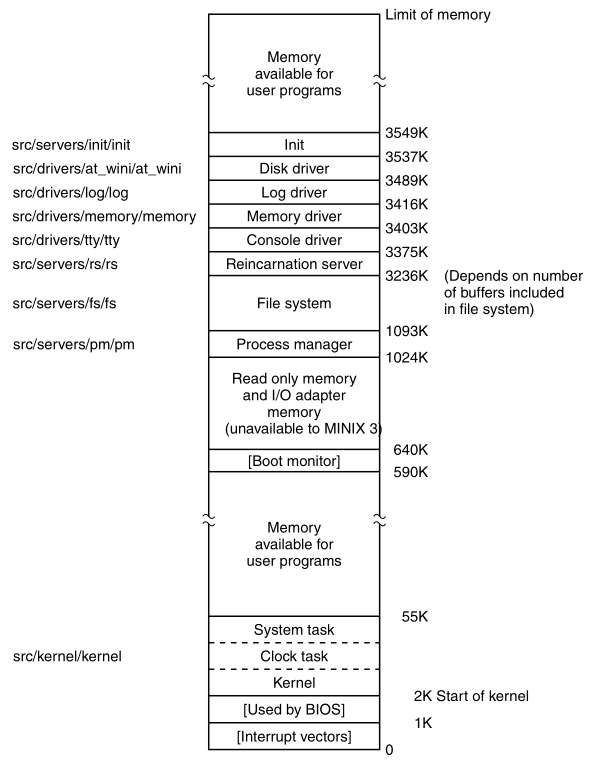
The kernel, servers, and drivers are files themselves,
independently compiled and linked programs,
listed on the left.
Sizes are approximate, and not to scale.
The kernel is loaded in low memory,
all the other parts of the boot image are loaded above 1 MB.
When user programs are run,
the available memory above the kernel will be used first.
When a new program will not fit there,
it will be loaded in the high memory range, above
init.
Details of memory quantity, of course, depend upon the system
configuration.
MINIX3 consists of several totally independent programs,
that communicate only by passing messages.
A procedure called panic, in the directory
src/servers/fs/
does not conflict with a procedure called panic in
src/servers/pm/
because they ultimately are linked into different executable files.
This modular structure makes it very easy to modify any part,
For example, one could modiy the file system,
without having these changes affect the process manager.
Or, to remove the file system altogether,
and to put it on a different machine as a file server,
communicating with user machines by sending messages over a network.
As another example of the modularity of MINIX3,
adding network support makes absolutely no difference to other
components,
such as the process manager, the file system, or the kernel.
Both an Ethernet driver and the inet server,
can be activated after the boot image is loaded;
they would appear with the processes started by
/etc/rc,
loaded into one of the “Memory available for user programs” regions.
This is very different than most monolithic operating systems!
A MINIX3 system may have networking enabled,
which can be used as a remote terminal, or an ftp and web server.
Only if you want to allow incoming logins to the MINIX3 system over the
network,
would any part of MINIX3, as described in the text, need
modification:
this is tty, the console driver,
which would need to be recompiled with pseudo terminals,
configured to allow remote logins.
Though most parts are modularly separate,
the three major pieces of the operating system do have some procedures
in common,
including a few of the library routines in src/lib/.
The include/ tree defines constants, macros, and
types.
The files in these directories are header or include files,
identified by the suffix .h,
and used by means of #include <...> statements in C
source files.
These statements are a built-in feature of the C language.
Include files make maintenance of a large system easier.
The POSIX standard requires many of these definitions,
and specifies in which files of the main include/
directory,
and its subdirectory include/sys/,
each required definition is to be found.
Headers likely to be needed for compiling user programs,
are mainly found in include/.
Files used primarily for compiling system programs and utilities,
are often in include/sys/.
A typical compilation, whether of a user program,
or part of the operating system,
will include files from both of these directories.
We discuss the files needed to compile the standard MINIX3 system,
first treating those in include/, and then those in
include/sys/.
The first headers to be considered are truly general purpose
ones.
They are not referenced directly,
by any of the C language source files for the MINIX3 system.
Rather, they are themselves included in other header files.
Each major component of MINIX3 has a master header file, such
as:
src/kernel/kernel.h, src/servers/pm/pm.h, or
src/servers/fs/fs.h.
Source code for each device driver includes a somewhat similar
file,
src/drivers/drivers.h.
These are included in every compilation of these components.
Show these in the actual source code!
For example, this part of a master header,
which ensures inclusion of header files,
needed by all C source files.
#include <minix/config.h>   /* MUST be first */
#include <ansi.h>           /* MUST be second */
#include <limits.h>
#include <errno.h>
#include <sys/types.h>
#include <minix/const.h>
#include <minix/type.h>
#include <minix/syslib.h>
#include "const.h"
Each master header starts with a similar section,
and includes most of the files shown there.
Note that two const.h files, one from the
include/ tree,
and one from the local directory, are referenced.
The master headers will be discussed again in other sections of the
book.
This preview is to emphasize that:
headers from several directories are used together.
In this section and the next one,
we will mention each of the files referenced here.
include/minix/config.h is processed first.
Next, the first header in include/,
ansi.h.
Whenever any part of the MINIX3 system is compiled;
This is the second header that is processed.
The purpose of ansi.h is:
to test whether the compiler meets the requirements of Standard C,
as defined by the International Organization for Standards.
Standard C is also often referred to as ANSI C,
(American National Standards Institute)
A Standard C compiler defines several macros,
that can then be tested in programs being compiled.
__STDC__ is such a macro,
It is defined by a standard compiler to have a value of 1,
just as if the C preprocessor had read a line like:
#define __STDC__ 1
The compiler in this version of MINIX3 conforms to Standard C,
though older versions did not.
The statement:
#define_ANSI
is processed if a Standard C compiler is in use.
ansi.h defines several macros in different ways,
depending upon whether the _ANSI macro is defined.
This is an example of a feature test macro.
Another feature test macro defined here is:
_POSIX_SOURCE.
This is required by POSIX.
Here we ensure that:
if other macros that imply POSIX conformance are defined,
that it is also defined.
When compiling a C program, the data types of the arguments,
and the return values of functions, must be known,
before code that references such data can be generated.
In a large program,
ordering of function definitions to meet this requirement is
difficult,
so C allows use of function prototypes,
to declare the arguments and return value types of a function,
before it is defined.
The most important macro in ansi.h is:
_PROTOTYPE.
This macro allows us to write function prototypes in the form
_PROTOTYPE (return-type function-name, (argument-type argument, ...))
and have this transformed by the C preprocessor into
return-type function-name(argument-type, argument, ...)
C/C++ include file conventions
Before we leave ansi.h let us mention one additional
feature.
The entire file (not initial comments) is enclosed between lines that
read:
#ifndef _ANSI_H
…
#endif /* _ANSI_H */
On the line immediately following the #ifndef,
the #ifndef _ANSI_H itself is defined.
A header file should be included only once in a compilation;
this construction ensures that, if it is included multiple times,
then the contents of the file will be ignored.
This technique is used in all the header files in the
include/ directory.
Two points about this deserve mention:
First, in all of the #ifndef ... #define
sequences,
for files in the master header directories,
the filename is preceded by an underscore,
for example: _ANSI_H.
Another header with the same name may exist,
within the C source code directories,
and the same mechanism will be used there,
but underscores will not be used.
Thus inclusion of a file from the master header directory,
will not prevent processing of another header file,
with the same name in a local directory.
Second, note that after the #ifndef the comment
/* _ANSI_H */ is not required.
Such comments can be helpful in keeping track of nested sections
like
#ifndef ... #endif and
#ifdef ... #endif
However, care is needed in writing such comments:
if incorrect, they are worse than no comment at all.
The second file in include/,
that is thus indirectly included in most MINIX3 source files,
is the limits.h header.
This file defines many basic sizes,
both language types, such as the number of bits in an integer,
as well as operating system limits, such as the length of a file name
(show this).
errno.h, is also included by most of the master
headers.
When a system call fails,
it contains the error numbers that are returned to user programs,
in the global variable errno
errno is also used to identify some internal
errors,
such as trying to send a message to a nonexistent task.
Functions must often return other integers, for example,
the number of bytes transferred during an I/O operation.
The MINIX3 solution is to return error numbers as negative values,
to mark them as error codes within the system,
and then to convert them to positive values,
before being returned to user programs.
The trick that is used, is that:
Each error code is defined in a line like:
#define EPERM (_SIGN 1).
The master header file for each part of the operating system defines the
_SYSTEM macro,
but _SYSTEM is never defined when a user program is
compiled.
If _SYSTEM is defined,
then _SIGN is defined as −;
otherwise it is given a null definition.
The next files are not in all the master headers,
but are used in many source files in MINIX3.
The most important is unistd.h.
This header defines many constants, most of which are required by
POSIX.
In addition, it includes prototypes for many C functions,
including all those used to access MINIX3 system calls.
Notice the numbering of standard in, standard out, and standard error!
Another widely used file is string.h,
which provides prototypes for many C functions used for string
manipulation.
The header signal.h defines the standard signal
names.
Several MINIX3-specific signals for operating system use are defined, as
well.
Operating systems functions are handled by independent processes,
rather than within a monolithic kernel,
thus we use signal-like communication between the system
components.
signal.h also contains prototypes for some signal-related
functions.
As we will see later, signal handling involves all parts of MINIX3.
fcntl.h symbolically defines parameters used in file
control operations.
For example, it allows one to use the macro O_RDONLY
instead of the numeric value 0, as a parameter to an open
call.
Although this file is referenced mostly by the file system,
its definitions are also needed in a number of places,
in the kernel and the process manager.
As we will see when we look at the device driver layer,
that the console and terminal interface of an operating system is
complex.
Different hardware interacts with the operating system and user
programs,
ideally in a standardized way.
termios.h defines constants, macros, and function
prototypes,
used for control of terminal-type I/O devices.
The most important structure is the termios
structure.
It contains flags to signal various modes of operation,
variables to set input and output transmission speeds,
and an array to hold special characters
(e.g., the INTR and KILL characters).
This structure is required by POSIX,
as are many of the macros and function prototypes defined in this
file.
However, as all-encompassing as the POSIX standard is meant to
be,
it does not provide everything one might want,
and the last part of the file, provides extensions to POSIX.
Some of these are of obvious value,
such as extensions to define standard baud rates of 57,600 baud and
higher,
and support for terminal display screen windows.
The POSIX standard does not forbid extensions,
as no reasonable standard can ever be all-inclusive.
But when writing a program in the MINIX3 environment,
which is intended to be portable to other environments,
some caution is required, to avoid the use of definitions specific to
MINIX3.
This is fairly easy to do.
In this file, and other files that define MINIX3-specific
extensions,
the use of the extensions is controlled by the statement:
#ifdef _MINIX
If the macro_MINIX is not defined,
then the compiler will not even see the MINIX3 extensions;
they will all be completely ignored.
Watchdog timers are supported by timers.h,
which is included in the kernel’s master header.
It defines a struct timer,
as well as prototypes of functions used to operate on lists of
timers.
It includes a typedef for tmr_func_t.
This data type is a pointer to a function.
Below that, its use is seen:
within a timer structure, used as an element in a list of timers,
one element is a tmr_func_t,
to specify a function to be called when the timer expires.
stdlib.h defines types, macros, and function
prototypes,
that are likely to be needed in the compilation of most C
programs.
It is one of the most frequently used headers in compiling user
programs,
although within the MINIX3 system source,
it is referenced by only a few files in the kernel.
stdio.h is familiar to everyone programming in C,
who has written a “Hello World!” program.
It is hardly used at all in system files.
Although, like stdlib.h, it is used in almost every user
program.
a.out.h defines the format in which executable programs
are stored on disk.
An exec structure is defined here,
and the information in this structure is used by the process
manager,
to load a new program image when an exec call is made.
Open both this file,
and an example of a C/C++ file binary.
Finally, stddef.h defines a few commonly used
macros.
Now let us go on to the subdirectory include/sys/.
The master headers for the main parts of the MINIX3 system,
all cause sys/types.h to be read immediately after reading
ansi.h.
sys/types.h defines many data types used by MINIX3.
The size, in bits, of some types on 16-bit and 32-bit systems:
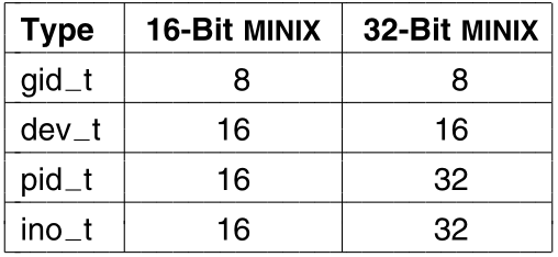
This image shows the way the sizes differ, in bits,
of a few types defined in this file,
when compiled for 16-bit or 32-bit processors.
_t
Note that all type names end with _t.
This is not just a MINIX3 convention;
it is a requirement of the POSIX standard.
This is an example of a reserved suffix,
and _t should not be used as a suffix of any other
name,
which is not a type name.
MINIX3 currently runs natively on 32-bit microprocessors,
but 64-bit processors will be increasingly important in the
future.
A type that is not provided by the hardware can be synthesized if
necessary.
The u64_t type is defined as struct
{u32_t[2]}.
This type is not needed very often in the current implementation,
but it can be useful.
For example, all disk and partition data (offsets and sizes)
is stored as 64 bit numbers, allowing for very large disks.
MINIX3 uses many type definitions,
that ultimately are interpreted by the compiler,
as a relatively small number of common types.
This is intended to help make the code more readable;
for example, a variable declared as the type dev_t is
recognizable,
as a variable meant to hold the major and minor device numbers,
that identify an I/O device.
For the compiler, declaring such a variable as a short would work
equally well.
Another thing to note is that:
many of the types defined here are matched by corresponding types,
with the first letter capitalized, for example, dev_t and
Dev_t.
The capitalized variants are all equivalent to type int to
the compiler;
these are provided to be used in function prototypes,
which must use types compatible with the int type,
to support K&R compilers.
The comments in types.h explain this in more detail.
One other item worth mention is the section of conditional code that
starts with
#if _EM_WSIZE == 2
Much conditional code has been removed from the source discussed in this
text.
This example was retained,
to point out one way that conditional definitions can be used.
The macro used, _EM_WSIZE,
is another example of a compiler-defined feature test macro.
It tells the word size for the target system in bytes.
#if ... #else ... #endif
is a way of specifying some definitions,
to make subsequent code compile correctly,
whether a 16-bit or 32-bit system is in use.
sys/sigcontext.h
Defines structures used to preserve and restore normal system
operation,
before and after execution of a signal handling routine,
and is used both in the kernel and the process manager.
sys/stat.h
Defines the structure which we saw in stat,
the filesystem system call and shell command.
This is returned by the stat and fstat system
calls,
as well as the prototypes of the functions stat and
fstat,
and other functions used to manipulate file properties.
It is referenced in several parts of the file system and the process
manager.
sys/dir.h defines the structure of a MINIX3 directory
entry.
It is only referenced directly once,
but this reference includes it in another header,
that is widely used in the file system.
It is important because, among other things,
it tells how many characters a file name may contain (60).
The sys/wait.h header defines macros used by the
wait and waitpid system calls,
which are implemented in the process manager.
MINIX3 supports tracing executables and analyzing core dumps,
with a debugger program,
and sys/ptrace.h defines the various operations
possible,
with the ptrace system call.
sys/svrctl.h defines data structures and macros used by
svrctl,
which is not really a system call, but is used like one.
svrctl is used to coordinate server-level processes,
as the system starts up.
The select system call permits waiting for input on
multiple channels,
for example, pseudo terminals waiting for network connections.
Definitions needed by this call are in sys/select.h.
We left discussion of sys/ioctl.h and related files
until last,
because they cannot be fully understood yet,
without also looking at a file in the next directory,
minix/ioctl.h.
The ioctl system call is used for device control
operations.
Device drivers need various kinds of control.
Indeed, the main difference between MINIX3, as described in this
book,
and other versions, is that for purposes of the book,
we describe MINIX3 with relatively few input/output devices.
Many others can be added,
such as network interfaces, SCSI controllers, and sound cards.
To make things more manageable, a number of small files,
each containing one group of definitions, are used.
They are all included by sys/ioctl.h,
which functions similarly to the master header above.
For example, sys/ioc_disk.h, and others:
sys/ioc_*.h
This and the other files included by sys_ioctl.h,
are located in the include/sys/ directory,
because they are considered part of the “published interface,”
meaning a programmer can use them in writing any program,
to be run in the MINIX3 environment.
However, they all depend upon additional macro definitions,
provided in minix/ioctl.h, which is included by each.
minix/ioctl.h should not be used by itself in writing
programs,
which is why it is in include/minix/ rather than
include/sys/.
The macros defined together by these files,
define how the various elements needed for each possible function,
are packed into a 32 bit integer to be passed to ioctl.
For example, disk devices need five types of operations,
as can be seen in sys/ioc_disk.h.
The alphabetic d parameter tells ioctl that
the operation is for a disk device,
an integer from 3 through 7 codes for the operation,
and the third parameter for a write or read
operation,
tells the size of the structure, in which data is to be passed.
In minix/ioctl.h,
8 bits of the alphabetic code,
are shifted 8 bits to the left,
the 13 least significant bits of the size of the structure,
are shifted 16 bits to the left,
and these are then logically ANDed with the small integer operation
code.
Another code in the most significant 3 bits of a 32-bit number,
encodes the type of return value.
Although this looks like a lot of work,
this work is done at compile time,
and makes for a much more efficient interface to the system call at run
time,
since the parameter actually passed,
is the most natural data type for the host machine CPU.
It does however, bring to mind a famous comment,
that Ken Thompson put into the source code of an early version of
UNIX:
/* You are not expected to understand this */
minix/ioctl.h also contains the prototype for the
ioctl system call.
This call is not directly invoked by programmers in many cases,
since the POSIX-defined functions prototyped in
include/termios.h
have replaced many uses of the old ioctl library
function,
for dealing with terminals, consoles, and similar devices.
Nevertheless, it is still necessary.
The POSIX functions for control of terminal devices,
are converted into ioctl system calls by the library.
In the next section, we will discuss files in:
include/minix/ and include/ibm/
directories,
which, as the directory names indicate, are unique to MINIX3,
and its implementation on IBM-type (really, Intel-type) computers.
The subdirectories include/minix/ and
include/ibm/
each contain header files specific to MINIX3.
Files in include/minix/ are needed,
for an implementation of MINIX3 on any platform,
although there are platform-specific alternative definitions within some
of them.
We have already discussed one file here, ioctl.h.
The files in include/ibm/ define structures and
macros,
that are specific to MINIX3 as implemented on IBM-type machines.
We will start with the minix/ directory.
In the previous section, it was noted that:
config.h is included in the master headers,
for all parts of the MINIX3 system,
and is thus the first file actually processed by the compiler.
On many occasions, when differences in hardware,
or the way the operating system is intended to be used,
require changes in the configuration of MINIX3,
editing this file, and recompiling the system is all that must be
done.
We suggest that, if you modify this file,
then you should also modify a comment,
to help identify the purpose of the modifications.
The user-settable parameters are all in the first part of the
file,
but some of these parameters are not intended to be edited here.
Another header file, minix/sys_config.h is included,
and definitions of some parameters are inherited from this file.
The programmers thought this was a good idea,
because a few files in the system need the basic definitions in
sys_config.h
without the rest of those in config.h.
In fact, there are many names in config.h which do not
begin with an underscore,
that are likely to conflict with names in common usage, such as
CHIP or INTEL,
that would likely be found in software ported to MINIX3, from another
operating system.
All of the names in sys_config.h begin with
underscores,
and conflicts are less likely.
MACHINE is actually configured as
_MACHINE_IBM_PC in sys_config.h,
which lists short alternatives for all possible values for
MACHINE.
Earlier versions of MINIX were ported to Sun, Atari, and MacIntosh
platforms,
and the full source code contains alternatives for alternative
hardware.
Most of the MINIX3 source code is independent of the type of
machine,
but an operating system always has some system-dependent code.
Other definitions in config.h allow customization,
for other needs in a particular installation.
For example, the number of buffers used by the file system, for the disk
cache,
should generally be as large as possible,
but a large number of buffers requires lots of memory.
Caching 128 blocks is considered minimal and satisfactory,
only for a MINIX3 installation on a system with less than 16 MB of
RAM;
for systems with ample memory, a much larger number can be put here.
If it is desired to use a modem, or log in over a network
connection,
then the NR_RS_LINES and NR_PTYS definitions
should be increased,
and the system recompiled.
The last part of config.h contains definitions that are
necessary,
but which should not be changed.
Many definitions here just define alternate names,
for constants defined in sys_config.h.
sys_config.h contains definitions likely to be needed by
a system programmer,
perhaps writing a new device driver.
You are not likely to need to change very much in this file,
with the possible exception of _NR_PROCS.
This controls the size of the process table.
If you want to use a MINIX3 system as a network server,
with many remote users, or many server processes running
simultaneously,
then you might need to increase this constant.
The next file is const.h,
which illustrates another common use of header files.
Here we find a variety of constant definitions,
that are not likely to be changed when compiling a new kernel,
but that are used in a number of places.
Defining them here helps to prevent errors,
that could be hard to track down,
if inconsistent definitions were made in multiple places.
Other files named const.h can be found elsewhere in the
MINIX3 source tree,
but they are for more limited use.
Similarly, definitions that are used only in the kernel,
are included in src/kernel/const.h.
Definitions that are used only in the file system,
are included in src/servers/fs/const.h.
The process manager uses src/servers/pm/const.h for its
local definitions.
Only those definitions that are used in more than one part of the
MINIX3 system,
are included in include/minix/const.h.
A few of the definitions in const.h are
noteworthy.
EXTERN is defined as a macro expanding into
extern.
Global variables, that are declared in header files,
and included in two or more files, are declared EXTERN, as
in:
EXTERN int who;
If the variable were declared just as
int who;
and included in two or more files,
then some linkers would complain about a multiply defined
variable.
Furthermore, the C reference manual explicitly forbids this
construction
(Kernighan and Ritchie, 1988).
To avoid this problem, it is necessary to have the declaration
read
extern int who;
in all places but one.
Using EXTERN prevents this problem,
by having it expand into extern everywhere that
const.h is included,
except following an explicit redefinition of EXTERN as the
null string.
This is done in each part of MINIX3,
by putting global definitions in a special file called
glo.h,
for example, src/kernel/glo.h,
which is indirectly included in every compilation.
Within each glo.h there is a sequence
#ifdef _TABLE
#undef EXTERN
#define EXTERN
#endif
and in the table.c files of each part of MINIX3 there is
a line:
#define _TABLE
preceding the #include section.
Thus, when the header files are included,
and expanded as part of the compilation of table.c,
extern is not inserted anywhere
(because EXTERN is defined as the null string
within table.c)
and storage for the global variables is reserved only in one
place,
in the object file table.o.
If you are new to C programming,
and do not quite understand what is going on here,
fear not; the details are really not important.
This is a polite way of rephrasing Ken Thompson’s famous comment cited
earlier.
Multiple inclusion of header files can cause problems for some
linkers,
because it can lead to multiple declarations for included
variables.
The EXTERN business is simply a way to make MINIX3 more
portable,
so it can be linked on other machines,
whose linkers do not accept multiply defined variables.
PRIVATE is defined as a synonym for
static.
Procedures and data,
that are not referenced outside the file in which they are
declared,
are always declared as PRIVATE,
to prevent their names from being visible,
outside the file in which they are declared.
As a general rule,
all variables and procedures should be declared with a local
scope,
if possible.
PUBLIC is defined as the null string.
An example from kernel/proc.c may help make this
clear.
The declaration:
PUBLIC void lock_dequeue(rp)
comes out of the C preprocessor as:
void lock_dequeue(rp)
which, according to the C language scope rules,
means that the function name lock_dequeue1 is exported from
the file,
and the function can be called from anywhere,
in any file linked into the same binary,
in this case, anywhere in the kernel.
Another function declared in the same file is:
PRIVATE void dequeue(rp)
which is preprocessed to become:
static void dequeue(rp)
This function can only be called from code in the same source
file.
PRIVATE and PUBLIC are not necessary in any
sense,
but are attempts to undo the damage caused by the C scope rules
(the default is that names are exported outside the file;
it should be just the reverse).
The rest of const.h defines numerical constants,
used throughout the system.
A section of const.h is devoted to machine or
configuration-dependent definitions.
Throughout the source code the basic unit of memory allocation is the
“click”.
Different values for the click size may be chosen,
for different processor architectures.
For Intel platforms it is 1024 bytes.
This file also contains the macros MAX and MIN, so we can say:
z = MAX(x, y);
to assign the larger of x and y to z.
type.h is included in every compilation,
by means of the master headers.
It contains a number of key type definitions,
along with related numerical values.
The first two structs define two different types of memory map,
one for local memory regions (within the data space of a process)
and one for remote memory areas, such as a RAM disk.
This is a good place to mention the concepts used in referring to
memory.
As we just mentioned, the click is the basic unit of measurement of
memory;
in MINIX3 for Intel processors a click is 1024 bytes.
Memory is measured as phys_clicks, which can be used by the
kernel,
to access any memory element anywhere in the system,
or as vir_clicks, used by processes other than the
kernel.
A vir_clicks memory reference is relative,
to the base of a segment of memory assigned to a particular
process,
and the kernel often has to make translations,
between virtual (process-based) and physical (RAM-based)
addresses.
The inconvenience of this, is offset by the fact that:
a process can do all its own memory references in
vir_clicks.
One might suppose that the same unit could be used
to specify the size of either type of memory,
but there is an advantage to using vir_clicks,
to specify the size of a unit of memory allocated to a process,
since when this unit is used, a check is done,
to be sure that no extra memory is accessed,
outside of what has been specifically assigned to the current
process.
This is a major feature of the protected mode of modern Intel
processors,
such as the Pentium family.
Its absence in the early 8086 and 8088 processors,
caused some headaches in the design of earlier versions of MINIX.
Another important structure defined here is
sigmsg.
When a signal is caught, the kernel has to arrange that,
the next time the signaled process gets to run,
it will run the signal handler,
rather than continuing execution where it was interrupted.
The process manager does most of the work of managing signals;
it passes a structure like this to the kernel when a signal is
caught.
The kinfo structure is used,
to convey information about the kernel,
to other parts of the system.
The process manager uses this information,
when it sets up its part of the process table.
Defines data structures and function prototypes,
for interprocess communication.
The most important definition in this file is
message.
While we could have defined message to be an array of some
number of bytes,
it is better programming practice to have it be another structure,
containing a union of the various message types that are possible.
Seven message formats, mess_1 through mess_8,
are defined
(type mess_6 is obsolete).
A message is a structure containing fields:
m_source, telling who sent the message,
m_type, telling what the message type is
(e.g., SYS_EXEC to the system task),
and the data fields.
The seven message types are shown:
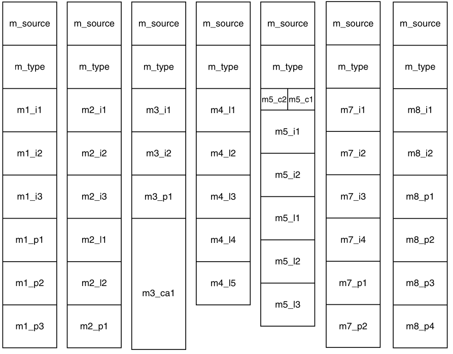
The seven message types used in MINIX3.
The sizes of message elements will vary,
depending upon the architecture of the machine;
this diagram illustrates sizes on CPUs with 32-bit pointers,
such as those of Pentium family members.
In the figure four message types,
the first two and the last two, seem identical.
Just in terms of size of the data elements they are identical,
but many of the data types are different.
It happens that on an Intel CPU with a 32-bit word size,
the int, long, and pointer data types are all 32-bit types,
but this would not necessarily be the case on another kind of
hardware.
Defining seven distinct formats,
makes it easier to recompile MINIX3 for a different architecture.
When it is necessary to send a message containing, for example,
three integers and three pointers (or three integers and two
pointers),
then the first format in the image just above is the one to use.
The same applies to the other formats.
How does one assign a value to the first integer in the first
format?
Suppose that the message is called x.
Then x.m_u refers to the union portion of the message
struct.
To refer to the first of the six alternatives in the union, we use
x.m_u.m_m1.
Finally, to get at the first integer in this struct we say
x.m_u.m_m1.m1i1.
This is quite a mouthful, so somewhat shorter field names are
defined,
as macros after the definition of message itself.
Thus x.m1_i1 can be used instead of
x.m_u.m_m1.m1i1.
The short names all have the form of:
the letter m,
the format number,
an underscore,
one or two letters indicating whether the field is an integer, pointer,
long, character, character array, or function,
and a sequence number, to distinguish multiple instances of the same
type within a message.
While discussing message formats,
this is a good place to note that an operating system, and its
compiler,
often have an “understanding” about things like the layout of
structures,
and this can make the implementer’s life easier.
In MINIX3, the int fields in messages are sometimes used to hold
unsigned data types.
In some cases this could cause overflow,
but the code was written assuming that knowledge,
that the MINIX3 compiler copies unsigned types to ints,
and vice versa, without changing the data, or generating code to detect
overflow.
A more explicit approach would be to replace each int field,
with a union of an int and an unsigned.
The same applies to the long fields in the messages;
some of them may be used to pass unsigned long data.
If you wish to port MINIX3 to a new platform,
then the exact format of the messages matters,
as does the behavior of the compiler.
Also defined in ipc.h,
are prototypes for the message passing primitives described
earlier.
In addition to the important send, receive,
sendrec, and notify primitives,
several others are defined.
None of these are much used;
they are relics of earlier stages of development of MINIX3.
They might disappear in a future release.
The non-blocking nb_send and nb_receive calls
have mostly been replaced by notify,
which was implemented later, and considered a better solution,
to the problem of sending or checking for a message, without
blocking.
The prototype for echo has no source or destination
field.
This primitive serves no useful purpose in production code,
but was useful during development,
to test the time it took to send and receive a message.
One other file in include/minix/,
syslib.h,
is almost universally used,
by means of inclusion in the master headers,
of all of the user-space components of MINIX3.
This file not included in the kernel’s master header file,
src/kernel/kernel.h,
because the kernel does not need library functions to access
itself.
syslib.h contains prototypes for C library functions,
called from within the operating system,
to access other operating system services.
We do not describe details of C libraries themselves in this
text,
but many library functions are standard and will be available for any C
compiler.
However, the C functions referenced by syslib.h are quite
specific to MINIX3,
and a port of MINIX3 to a new system, with a different compiler,
requires porting these library functions.
Fortunately this is not difficult,
since most of these functions simply extract the parameters of the
function call,
and insert them into a message structure,
then send the message and extract the results from the reply
message.
Many of these library functions are defined in a dozen or fewer lines of
C code.
Noteworthy in this file, are four macros for accessing I/O
ports,
for input or output, using byte or word data types,
and the prototype of the sys_sdevio function,
to which all four macros refer.
Providing a way for device drivers to make requests,
like reading and writing of I/O ports by the kernel,
is an essential part of the MINIX3 project,
which aims to move all such drivers to user space.
A few functions, which could have been defined in
syslib.h,
are in a separate file, sysutil.h,
because their object code is compiled into a separate library.
Two functions prototyped here need a little more explanation.
The first is printf.
If you have experience programming in C,
then you will recognize that printf is a standard library
function,
referenced in almost all programs.
This is not the printf function you think it is,
however.
The version of printf in the standard library cannot be
used within system components.
Among other things, the standard printf is intended to
write to standard output,
and must be able to format floating point numbers.
Using standard output would require going through the file system,
but for printing messages when there is a problem,
and a system component needs to display an error message,
it is desirable to be able to do this without assistance,
from any other system components.
Also, support for the full range of format specifications,
which are usable with the standard printf,
would bloat the code for no useful purpose.
So a simplified version of printf,
that does only what is needed by operating system components,
is compiled into the system utilities library.
This is found by the compiler,
in a place that will depend upon the platform;
for 32-bit Intel systems it is
/usr/lib/i386/libsysutil.a.
When the file system, the process manager, or another part of the
operating system,
is linked to library functions,
this version is found before the standard library is searched.
On the next line is a prototype for kputc.
This is called by the system version of printf,
to do the work of displaying characters on the console.
However, more tricky business is involved here.
kputc is defined in several places.
There is a copy in the system utilities library,
which will be the one used by default.
But several parts of the system define their own versions.
We will see one when we study the console interface in the next
chapter.
The log driver also defines its own version.
The log driver is not described in detail here.
There is even a definition of kuptc in the kernel
itself,
but this is a special case.
The kernel does not use printf.
A special printing function, kprintf,
is defined as part of the kernel,
and is used when the kernel needs to print.
When a process needs to execute a MINIX3 system call,
it sends a message to the process manager (PM for short),
or the file system (FS for short).
Each message contains the number of the system call desired.
These numbers are defined in the next file, callnr.h.
Some numbers are not used;
these are reserved for calls not yet implemented,
or represent calls implemented in other versions,
which are now handled by library functions.
Near the end of the file some call numbers are defined,
that do not correspond to calls we showed before.
svrctl (which was mentioned earlier), ksig,
unpause, revive, and
task_reply
are used only within the operating system itself.
The system call mechanism is a convenient way to implement these.
Because they will not be used by external programs,
these “system calls,” may be modified in new versions of MINIX3,
without fear of breaking user programs.
The next file is com.h.
One interpretation of the file name is that is stands for common,
another is that it stands for communication.
This file provides common definitions,
used for communication between servers and device drivers.
Task numbers are defined.
To distinguish them from process numbers,
task numbers are negative.
Process numbers are defined for the processes that are loaded in the
boot image.
Note these are slot numbers in the process table;
they should not be confused with process id (PID) numbers.
The next section of com.h defines how notify messages
are constructed,
to carry out a notify operation.
The process numbers are used in generating the value that is passed in
the m_type field of the message.
The message types for notifications and other messages defined in this
file are built by combining a base value that signifies a type category
with a small number that indicates the specific type.
The rest of this file is a compendium of macros that translate
meaningful identifiers into the cryptic numbers that identify message
types and field names.
devio.h defines types and constants that support
user-space access to I/O ports, as well as some macros that make it
easier to write code that specifies ports and values.
dmap.h defines a struct and an array of that struct,
both named dmap.
This table is used to relate major device numbers to the functions that
support them.
Major and minor device numbers for the memory device driver and major
device numbers for other important device drivers are also defined.
u64.h provides support for 64-bit integer arithmetic
operations,
necessary to manipulate disk addresses on high capacity disk
drives.
These were not even dreamed of when UNIX , the C language, Pentium-class
processors, and MINIX were first conceived.
A future version of MINIX3 may be written in a language that has
built-in support for 64-bit integers on CPUs with 64-bit registers;
until then, the definitions in u64.h provide a
work-around.
keymap.h defines the structures used to implement
specialized keyboard layouts for the character sets needed for different
languages.
It is also needed by programs which generate and load these tables.
bitmap.h provides a few macros to make operations like
setting, resetting, and testing bits easier.
Finally, partition.h defines the information needed by
MINIX3 to define a disk partition, either by its absolute byte offset
and size on the disk, or by a cylinder, head, sector address.
The u64_t type is used for the offset and size, to allow
use of large disks.
This file does not describe the layout of a partition table on a disk,
the file that does that is in the next directory.
The last specialized header directory we will consider,
include/ibm/,
contains several files which provide definitions related to the IBM PC
family of computers.
Since the C language knows only memory addresses, and has no provision
for accessing I/O port addresses, the library contains routines written
in assembly language to read and write from ports.
The various routines available are declared in
ibm/portio.h.
All possible input and output routines for byte, integer, and long data
types, singly or as strings, are available, from inb (input
one byte) to outsl (output a string of longs).
Low-level routines in the kernel may also need to disable or re-enable
CPU interrupts, which are also actions that C cannot handle.
The library provides assembly code to do this, and
intr_disable and intr_enable are declared.
The next file in this directory is interrupt.h, which
defines port address and memory locations used by the interrupt
controller chip and the BIOS of PC-compatible systems.
Finally, more I/O ports are defined in ports.h.
This file provides addresses needed to access the keyboard interface and
the timer chip used by the clock chip.
bios.h, memory.h, and
partition.h are copiously commented and are worth reading
if you would like to know more about memory use or disk partition
tables.
cmos.h, cpu.h, and int86.h
provide additional information on ports, CPU flag bits, and calling BIOS
and DOS services in 16-bit mode.
Finally, diskparm.h defines a data structure needed for
formatting a floppy disk.
Now let us dive in and see what the code in src/kernel/
looks like.
In the previous two sections we structured our discussion around an
excerpt from a typical master header.
We will look first at the real master header for the kernel,
kernel.h.
It begins by defining three macros.
The first, _POSIX_SOURCE, is a feature test macro defined
by the POSIX standard itself.
All such macros are required to begin with the underscore character,
_.
The effect of defining the _POSIX_SOURCE macro is to ensure
that all symbols required by the standard and any that are explicitly
permitted, but not required, will be visible, while hiding any
additional symbols that are unofficial extensions to POSIX.
We have already mentioned the next two definitions: the
_MINIX macro overrides the effect of
_POSIX_SOURCE for extensions defined by MINIX3, and
_SYSTEM can be tested wherever it is important to do
something differently when compiling system code, as opposed to user
code, such as changing the sign of error codes.
kernel.h then includes other header files from
include/ and its subdirectories include/sys/,
include/minix/, and include/ibm/ including all
those referred to in the master header above.
We have discussed all of these files in the previous two sections.
Finally, six additional headers from the local directory,
src/kernel/, are included, their names included in quote
characters.
kernel.h makes it possible to guarantee that all source
files share a large number of important definitions by writing the
single line:
#include "kernel.h"
in each of the other kernel source files.
Since the order of inclusion of header files is sometimes important,
kernel.h also ensures that this ordering is done correctly,
once and forever.
This carries to a higher level the “get it right once, then forget the
details” technique embodied in the header file concept.
Similar master headers are provided in source directories for other
system components, such as the file system and the process manager.
Now let us proceed to look at the local header files included in
kernel.h.
First we have yet another file named config.h, which,
analogous to the system-wide file include/minix/config.h,
must be included before any of the other local include files.
Just as we have files const.h and type.h in
the common header directory include/minix/, we also have
files const.h.
and type.h in the kernel source directory,
src/kernel/.
The files in include/minix/ are placed there because they
are needed by many parts of the system, including programs that run
under the control of the system.
The files in src/kernel/ provide definitions needed only
for compilation of the kernel.
The FS, PM, and other system source directories also contain
const.h and type.h files to define constants
and types needed only for those parts of the system.
Two of the other files included in the master header,
proto.h and glo.h,
have no counterparts in the main include/
directories,
but we will find that they, too, have counterparts used in compiling the
file system and the process manager.
The last local header included in kernel.h is another
ipc.h.
Since this is the first time it has come up in our discussion,
note at the beginning of kernel/config.h there is a:
#ifndef ... #define sequence,
to prevent trouble if the file is included multiple times.
We have seen the general idea before.
But note here that the macro defined here is CONFIG_H
without an underscore.
Thus it is distinct from the macro _CONFIG_H
defined in include/minix/config.h.
The kernel’s version of config.h gathers in one place a
number of definitions that are unlikely to need changes if your interest
in MINIX3 is studying how an operating system works, or using this
operating system in a conventional general-purpose computer.
However, suppose you want to make a really tiny version of MINIX3 for
controlling a scientific instrument or a home-made cellular
telephone.
The definitions on allow selective disabling of kernel calls.
Eliminating unneeded functionality also reduces memory requirements
because the code needed to handle each kernel call is conditionally
compiled using the definitions.
If some function is disabled, the code needed to execute it is omitted
from the system binary.
For example, a cellular telephone might not need to fork off new
processes, so the code for doing so could be omitted from the executable
file, resulting in a smaller memory footprint.
Most other constants defined in this file control basic
parameters.
For example, while handling interrupts a special stack of size
K_STACK_BYTES is used.
The space for this stack is reserved within mpx386.s, an
assembly language file.
In const.h a macro for converting virtual addresses
relative to the base of the kernel’s memory space to physical addresses
is defined.
A C function, umap_local, is defined elsewhere in the
kernel code so the kernel can do this conversion on behalf of other
components of the system, but for use within the kernel the macro is
more efficient.
Several other useful macros are defined here, including several for
manipulating bitmaps.
An important security mechanism built into the Intel hardware is
activated by two macro definition lines here.
The processor status word (PSW) is a CPU register, and I/O Protection
Level (IOPL) bits within it define whether access to the interrupt
system and I/O ports is allowed or denied.
Different PSW values are defined that determine this access for ordinary
and privileged processes.
These values are put on the stack as part of putting a new process in
execution.
In the next file we will consider, type.h uses two
quantities, base address and size, to uniquely specify an area of
memory.
type.h defines several other prototypes and structures
used in any implementation of MINIX3.
For example, two structures, kmessages, used for diagnostic
messages from the kernel, and randomness, used by the
random number generator, are defined.
type.h also contains several machine-dependent type
definitions.
To make the code shorter and more readable we have removed conditional
code and definitions for other CPU types.
But you should recognize that definitions like the
stackframe_s structure, which defines how machine registers
are saved on the stack, is specific to Intel 32-bit processors.
For another platform the stackframe_s structure would be
defined in terms of the register structure of the CPU to be used.
Another example is the segdesc_s structure, which is part
of the protection mechanism that keeps processes from accessing memory
regions outside those assigned to them.
For another CPU the segdesc_s structure might not exist at
all, depending upon the mechanism used to implement memory
protection.
Another point to make about structures like these is that making sure
all the required data is present is necessary, but possibly not
sufficient for optimal performance.
The stackframe_s must be manipulated by assembly language
code.
Defining it in a form that can be efficiently read or written by
assembly language code reduces the time required for a context
switch.
The next file, proto.h, provides prototypes of all
functions that must be known outside of the file in which they are
defined.
All are written using the _PROTOTYPE macro discussed in the
previous section, and thus the MINIX3 kernel can be compiled either with
a classic C (Kernighan and Ritchie) compiler, such as the original
MINIX3 C compiler, or a modern ANSI Standard C compiler, such as the one
which is part of the MINIX3 distribution.
A number of these prototypes are system-dependent, including interrupt
and exception handlers and functions that are written in assembly
language.
In glo.h we find the kernel’s global variables.
The purpose of the macro EXTERN was described in the
discussion of include/minix/const.h.
It normally expands into extern.
Note that many definitions in glo.h are preceded by this
macro.
The symbol EXTERN is forced to be undefined when this file
is included in table.c, where the macro_TABLE
is defined.
Thus the actual storage space for the variables defined this way is
reserved when glo.h is included in the compilation of
table.c.
Including glo.h in other C source files makes the variables
in table.c known to the other modules in the kernel.
Some of the kernel information structures here are used at
startup.
aout will hold the address of an array of the headers of
all of the MINIX3 system image components.
Note that these are physical addresses, that is, addresses relative to
the entire address space of the processor.
As we will see later, the physical address of aout will be
passed from the boot monitor to the kernel when MINIX3 starts up, so the
startup routines of the kernel can get the addresses of all MINIX3
components from the monitor’s memory space.
kinfo is also an important piece of information.
Recall that the structure was defined in
include/minix/type.h.
Just as the boot monitor uses aout to pass information
about all processes in the boot image to the kernel, the kernel fills in
the fields of kinfo with information about itself that
other components of the system may need to know about.
The next section of glo.h contains variables related to
control of process and kernel execution.
prev_ptr1, proc_ptr1, and
next_ptr point to the process table entries of the
previous, current, and next processes to run.
bill_ptr also points to a process table entry; it shows
which process is currently being billed for clock ticks used.
When a user process calls the file system, and the file system is
running, proc_ptr points to the file system process.
However, bill_ptr will point to the user making the call,
since CPU time used by the file system is charged as system time to the
caller.
We have not actually heard of a MINIX system whose owner charges others
for their use of CPU time, but it could be done.
The next variable, k_reenter, is used to count nested
executions of kernel code, such as when an interrupt occurs when the
kernel itself, rather than a user process, is running.
This is important, because switching context from a user process to the
kernel or vice versa is different (and more costly) than reentering the
kernel.
When an interrupt service completes, it is important for it to determine
whether control should remain with the kernel, or if a user-space
process should be restarted.
This variable is also tested by some functions, which disable and
re-enable interrupts, such as lock_enqueue.
If such a function is executed when interrupts are disabled already, the
interrupts should not be re-enabled when re-enabling is not
wanted.
Finally, in this section there is a counter for lost clock ticks.
How a clock tick can be lost, and what is done about it, will be
discussed when we discuss the clock task.
The last few variables defined in glo.h, are declared
here because they must be known throughout the kernel code, but they are
declared as extern rather than as EXTERN
because they are initialized variables, a feature of the C
language.
The use of the EXTERN macro is not compatible with C-style
initialization, since a variable can only be initialized once.
Tasks that run in kernel space, currently just the clock task and the
system task, have their own stacks within t_stack.
During interrupt handling, the kernel uses a separate stack, but it is
not declared here, since it is only accessed by the assembly language
level routine that handles interrupt processing, and does not need to be
known globally.
The last file included in kernel.h, and thus used in
every compilation, is ipc.h.
It defines various constants used in interprocess communication.
We will discuss these later when we get to the file where they are used,
kernel/proc.c.
Several more kernel header files are widely used, although not so
much that they are included in kernel.h.
The first of these is proc.h, which defines the kernel’s
process table.
The complete state of a process is defined by the process’ data in memory, plus the information in its process table slot.
The contents of the CPU registers are stored here when a process is
not executing and then are restored when execution resumes.
This is what makes possible the illusion that multiple processes are
executing simultaneously and interacting, although at any instant a
single CPU can be executing instructions of only one process.
The time spent by the kernel saving and restoring the process state
during each context switch is necessary, but obviously this is time
during which the work of the processes themselves is suspended.
For this reason these structures are designed for efficiency.
As noted in the comment at the beginning of proc.h, many
routines written in assembly language also access these structures, and
another header, sconst.h, defines offsets to fields in the
process table for use by the assembly code.
Thus changing a definition in proc.h may necessitate a
change in sconst.h.
Before going further we should mention that, because of MINIX3’s
microkernel structure, the process table we will discuss is here is
paralleled by tables in PM and FS which contain per-process entries
relevant to the function of these parts of MINIX3.
Together, all three of these tables are equivalent to the process table
of an operating system with a monolithic structure, but for the moment
when we speak of the process table we will be talking about only the
kernel’s process table.
The others will be discussed in later chapters.
Each slot in the process table is defined as a
struct proc.
Each entry contains storage for the process’ registers, stack pointer,
state, memory map, stack limit, process id, accounting, alarm time, and
message info.
The first part of each process table entry is a
stackframe_s structure.
A process that is already in memory is put into execution by loading its
stack pointer with the address of its process table entry and popping
all the CPU registers from this struct.
There is more to the state of a process than just the CPU registers
and the data in memory, however.
In MINIX3, each process has a pointer to a priv structure
in its process table slot.
This structure defines allowed sources and destinations of messages for
the process and many other privileges.
We will look at details later.
For the moment, note that each system process has a pointer to a unique
copy of this structure, but user privileges are all equal.
The pointers of all user processes point to the same copy of the
structure.
There is also a byte-sized field for a set of bit flags,
p_rts_flags.
The meanings of the bits will be described below.
Setting any bit to 1 means a process is not runnable, so a zero in this
field indicates a process is ready.
Each slot in the process table provides space for information that
may be needed by the kernel.
For example, the p_max_priority field, tells which
scheduling queue the process should be queued on when it is ready to run
for the first time.
Because the priority of a process may be reduced if it prevents other
processes from running, there is also a p_priority field
which is initially set equal to p_max_priority.
p_priority is the field that actually determines the queue
used each time the process is ready.
The time used by each process is recorded in the two
clock_t variables.
This information must be accessed by the kernel and it would be
inefficient to store this in a process’ own memory space, although
logically that could be done.
p_nextready, is used to link processes together on the
scheduler queues.
The next few fields hold information related to messages between
processes.
When a process cannot complete a send, because the destination is not
waiting, the sender is put onto a queue pointed to by the destination’s
p_caller_q pointer.
That way, when the destination finally does a receive, it is easy to
find all the processes wanting to send to it.
The p_q_link field is used to link the members of the queue
together.
The rendezvous method of passing messages is made possible by the
storage space reserved.
When a process does a receive, and there is no message waiting for it,
it blocks, and the number of the process it wants to receive from is
stored in p_getfrom.
Similarly, p_sendto holds the process number of the
destination, when a process does a send, and the recipient is not
waiting.
The address of the message buffer is stored in
p_messbuf.
The penultimate field in each process table slot is
p_pending, a bitmap used to keep track of signals that have
not yet been passed to the process manager (because the process manager
is not waiting for a message).
Finally, the last field in a process table entry is a character
array, p_name, for holding the name of the process.
This field is not needed for process management by the kernel.
MINIX3 provides various debug dumps triggered by pressing a special key
on the console keyboard.
Some of these allow viewing information about all processes, with the
name of each process printed along with other data.
Having a meaningful name associated with each process makes
understanding and debugging kernel operation easier.
Following the definition of a process table slot, come definitions of
various constants used in its elements.
The various flag bits that can be set in p_rts_flags are
defined and described.
If the slot is not in use, SLOT_FREE is set.
After a fork, NO_MAP is set to prevent the child process
from running until its memory map has been set up.
SENDING and RECEIVING indicate that the process is blocked trying to
send or receive a message.
SIGNALED and SIG_PENDING indicate that signals have been
received, and P_STOP provides support for tracing.
NO_PRIV is used to temporarily prevent a new system process
from executing until its setup is complete.
the number of scheduling queues and allowable values for the
p_priority field are defined next.
In the current version of this file, user processes are allowed to be
given access to the highest priority queue; this is probably a
carry-over from the early days of testing drivers in user space and
MAX_USER_Q should probably adjusted to a lower priority
(larger number).
Next come several macros that allow addresses of important parts of
the process table to be defined as constants at compilation time, to
provide faster access at run time, and then more macros for run time
calculations and tests.
The macro proc_addr is provided, because it is not possible
to have negative subscripts in C.
Logically, the array proc should go from
−NR_TASKS to +NR_PROCS.
Unfortunately, in C it must start at 0, so proc[0] refers
to the most negative task, and so forth.
To make it easier to keep track of which slot goes with which process,
we can write
rp = proc_addr(n);
to assign to rp the address of the process slot for
process n, either positive or negative.
The process table itself is defined here as an array of
proc
structures,proc[NR_TASKS + NR_PROCS].
Note that NR_TASKS is defined in
include/minix/com.h and the constant NR_PROCS
is defined in include/minix/config.h.
Together these set the size of the kernel’s process table.
NR_PROCS can be changed to create a system capable of
handling a larger number of processes, if that is necessary (e.g., on a
large server).
Finally, several macros are defined to speed access.
The process table is accessed frequently, and calculating an address in
an array requires slow multiplication operations, so an array of
pointers to the process table elements, pproc_addr, is
provided.
The two arrays rdy_head and rdy_tail are used
to maintain the scheduling queues.
For example, the first process on the default user queue is pointed to
by rdy_head[USER_Q].
As we mentioned at the beginning of the discussion of
proc.h there is another file sconst.h, which
must be synchronized with proc.h if there are changes in
the structure of the process table.
sconst.h defines constants used by assembler code,
expressed in a form usable by the assembler.
All of these are offsets into the stackframe_s structure
portion of a process table entry.
Since assembler code is not processed by the C compiler, it is simpler
to have such definitions in a separate file.
Also, since these definitions are all machine dependent, isolating them
here simplifies the process of porting MINIX3 to another processor which
will need a different version of sconst.h.
Note that many offsets are expressed as the previous value plus W, which
is set equal to the word size.
This allows the same file to serve for compiling a 16-bit or 32-bit
version of MINIX3.
Duplicate definitions create a potential problem.
Header files are supposed to allow one to provide a single correct set
of definitions and then proceed to use them in many places without
devoting a lot of further attention to the details.
Obviously, duplicate definitions, like those in proc.h and
sconst.h, violate that principle.
This is a special case, of course, but as such, special attention is
required if changes are made to either of these files to ensure the two
files remain consistent.
The system privileges structure, priv, that was
mentioned briefly in the discussion of the process table is fully
defined in priv.h.
First there is a set of flag bits, s_flags, and then come
the s_trap_mask, s_ipc_from,
s_ipc_to, and s_call_mask fields which define
which system calls may be initiated, which processes messages may be
received from or sent to, and which kernel calls are allowed.
The priv structure is not part of the process table,
rather each process table slot has a pointer to an instance of it.
Only system processes have private copies; user processes all point to
the same copy.
Thus, for a user process the remaining fields of the structure are not
relevant, as sharing them does not make sense.
These fields are bitmaps of pending notifications, hardware interrupts,
and signals, and a timer.
It makes sense to provide these here for system processes,
however.
User processes have notifications, signals, and timers managed on their
behalf by the process manager.
The organization of priv.h is similar to that of
proc.h.
After the definition of the priv structure come macros
definitions for the flag bits, some important addresses known at compile
time, and some macros for address calculations at run time.
Then the table of priv structures,
priv[NR_SYS_PROCS], is defined, followed by an array of
pointers, ppriv_addr[NR_SYS_PROCS].
The pointer array provides fast access, analogous to the array of
pointers that provides fast access to process table slots.
The value of STACK_GUARD is a pattern that is easily
recognizable.
Its use will be seen later; the reader is invited to search the Internet
to learn about the history of this value.
The last item in priv.h is a test to make sure that
NR_SYS_PROCS has been defined to be larger than the number
of processes in the boot image.
The #error line will print a message if the test condition tests
true.
Although behavior may be different with other C compilers, with the
standard MINIX3 compiler this will also abort the compilation.
The F4 key triggers a debug dump that shows some of the information
in the privilege table.
The image below shows a few lines of this table for some representative
processes.
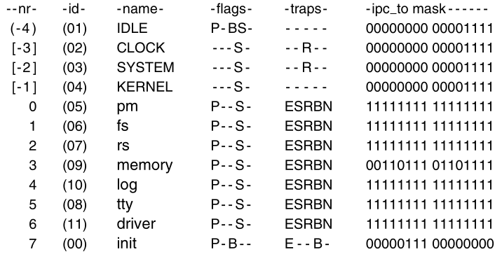
Part of a debug dump of the privilege table.
The clock task, file server fs, tty, and
init processes privileges are typical of tasks, servers,
device drivers, and user processes, respectively.
The bitmap is truncated to 16 bits.
The flags entries mean P: preemptable, B: billable, S: system.
The traps mean E: echo, S: send, R: receive, B: both, N:
notification.
The bitmap has a bit for each of the NR_SYS_PROCS (32)
system processes allowed, the order corresponds to the id field.
(In the figure only 16 bits are shown, to make it fit the page better.)
All user processes share id 0, which is the left-most bit
position.
The bitmap shows that user processes such as init can send
messages only to the process manager, file system, and reincarnation
server, and must use sendrec.
The servers and drivers shown in the figure can use any of the ipc
primitives and all but memory can send to any other process.
Another header that is included in a number of different source files
is protect.h.
Almost everything in this file deals with architecture details of the
Intel processors that support protected mode (the 80286, 80386, 80486,
and the Pentium series).
A detailed description of these chips is beyond the scope of this
book.
Suffice it to say that they contain internal registers that point to
descriptor tables in memory.
Descriptor tables define how system resources are used and prevent
processes from accessing memory assigned to other processes.
The architecture of 32-bit Intel processors also provides for four
privilege levels, of which MINIX3 takes advantage of three.
These are defined symbolically.
The most central parts of the kernel, the parts that run during
interrupts and that manage context switches, always run with
INTR_PRIVILEGE.
Every address in the memory and every register in the CPU can be
accessed by a process with this privilege level.
The tasks run at TASK_PRIVILEGE level, which allows them to
access I/O but not to use instructions that modify special registers,
like those that point to descriptor tables.
Servers and user processes run at USER_PRIVILEGE
level.
Processes executing at this level are unable to execute certain
instructions, for example those that access I/O ports, change memory
assignments, or change privilege levels themselves.
The concept of privilege levels will be familiar to those who are familiar with the architecture of modern CPUs, but those who have learned computer architecture through study of the assembly language of low-end microprocessors may not have encountered such features.
One header file in kernel/ has not yet been described:
system.h, and we will postpone discussing it until later in
this chapter when we describe the system task, which runs as an
independent process, although it is compiled with the kernel.
For now we are through with header files,
and are ready to dig into the *.c C language source
files.
The first of these that we will look at is
table.c.
Compilation of this produces no executable code,
but the compiled object file table.o will contain all the
kernel data structures.
We have already seen many of these data structures defined,
in glo.h and other headers.
The macro _TABLE is defined,
immediately before the #include statements.
This definition causes EXTERN to become defined as the null
string,
and storage space to be allocated for all the data declarations preceded
by EXTERN.
In addition to the variables declared in header files,
there are two other places where global data storage is allocated.
Some definitions are made directly in table.c.
The stack space needed by kernel components is defined,
and the total amount of stack space for tasks is reserved as the array
t_stack[TOT_STACK_SPACE].
The rest of table.c defines many constants related to
properties of processes,
such as the combinations of flag bits, call traps,
and masks that define to whom messages and notifications can be
sent.
Following this are masks to define the kernel calls allowed for various
processes.
The process manager and file server are all allowed unique
combinations.
The reincarnation server is allowed access to all kernel calls,
not for its own use, but because as the parent of other system
processes,
it can only pass to its children, subsets of its own privileges.
Drivers are given a common set of kernel call masks,
except for the RAM disk driver which needs unusual access to memory.
Note that the comment that mentions the “system services
manager”
should say “reincarnation server”;
the name was changed during development,
and some comments still refer to the old name.
Finally, the image table is defined.
It has been put here, rather than in a header file,
because the trick with EXTERN used to prevent multiple
declarations,
does not work with initialized variables;
that is, you may not say:
extern int x = 3;
anywhere.
The image table provides details needed to initialize all of the
processes that are loaded from the boot image.
It will be used by the system at startup.
As an example of the information contained here,
consider the field labeled qs.
This shows the size of the quantum assigned to each process.
Ordinary user processes, as children of init,
get to run for 8 clock ticks.
The CLOCK and SYSTEM tasks are allowed to run
for 64 clock ticks if necessary.
They are not really expected to run that long before blocking,
but unlike user-space servers and drivers,
they cannot be demoted to a lower-priority queue,
if they prevent other processes from getting a chance to run.
If a new process is to be added to the boot image,
then a new row must be provided in the image table.
An error in matching the size of image to other constants is intolerable
and cannot be permitted.
At the end of table.c tests are made for errors, using a
little trick.
The array dummy is declared here twice.
In each declaration, the size of dummy will be impossible,
and will trigger a compiler error if a mistake has been made.
Since dummy is declared as extern,
no space is allocated for it here (or anywhere).
Since it is not referenced anywhere else in the code,
this will not bother the compiler.
Additional global storage is allocated at the end of the assembly
language file mpx386.s.
Although it will require skipping ahead several pages in the listing to
see this,
it is appropriate to discuss this now, since we are on the subject of
global variables.
The assembler directive .sect .rom is used to
put a magic number
(to identify a valid MINIX3 kernel) at the very beginning of the
kernel’s data segment.
A .sect bss assembler directive and the
.space pseudo-instruction,
are also used here to reserve space for the kernel’s stack.
The .comm pseudo-instruction labels several words at the
top of the stack,
so they may be manipulated directly.
We will come back to mpx386.s in a few pages,
after we have discussed bootstrapping MINIX3.
See source files in the source repository: boot/*
It is almost time to start looking at the executable code, but not
quite.
Before we do that, let us take a few moments to understand how MINIX3 is
loaded into memory.
It is loaded from a disk,
but the process is not completely trivial,
and the exact sequence of events depends on whether the disk is
partitioned or not.
The image below shows how diskettes and partitioned disks are laid
out:
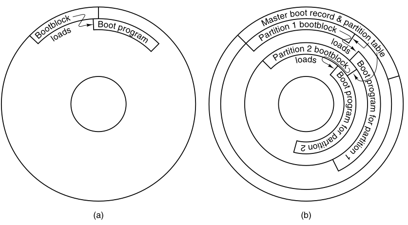
Disk structures used for bootstrapping.
(a) Un-partitioned disk.
The first sector is the bootblock.
(b) Partitioned disk.
The first sector is the master boot record,
also called masterboot or mbr.
When the system is started,
The hardware runs a program in ROM,
which reads the first sector of the boot disk,
copies it to a fixed location in memory,
and executes the code found there.
On an un-partitioned MINIX3 diskette,
the first sector is a bootblock which loads the boot program, as (a)
above.
Hard disks are partitioned.
The program on the first sector is called masterboot on
MINIX systems.
It first re-locates itself to a different memory region,
then reads the partition table,
loaded with it from the first sector.
Then it loads and executes the first sector of the active partition, as
shown in (b).
Normally one, and only one, partition is marked active.
A MINIX3 partition has the same structure as an un-partitioned MINIX3
diskette,
with a bootblock that loads the boot program.
The bootblock code is the same for an un-partitioned or a partitioned
disk.
Since the masterboot program relocates itself,
the bootblock code can be written to run at the same memory address
where masterboot is originally loaded.
The actual situation can be a little more complicated than the figure
shows,
because a partition may contain sub-partitions.
In this case, the first sector of the partition will be another master
boot record,
containing the partition table for the sub-partitions.
Eventually however, control will be passed to a boot sector,
the first sector on a device that is not further subdivided.
On a diskette, the first sector is always a boot sector.
MINIX3 does allow a form of partitioning of a diskette,
but only the first partition may be booted;
there is no separate master boot record,
and sub-partitions are not possible.
Partitioned and non-partitioned diskettes to be mounted in the same
way.
The main use for a partitioned floppy disk is that:
it provides a convenient way to divide an installation disk,
into a root image to be copied to a RAM disk,
and a mounted portion that can be dismounted when no longer
needed,
in order to free the diskette drive for continuing the installation
process.
The MINIX3 boot sector is modified at the time it is written to the
disk,
by a special program called installboot which writes the
boot sector,
and patches into it the disk address of a file named boot,
on its partition or sub-partition.
In the installed OS,
the location for the boot program is in a directory of the same
name,
that is, /boot/boot.
The source code is /boot/boot.c.
But it could be anywhere,
the patching of the boot sector just mentioned,
locates the disk sectors from which it is to be loaded.
This is necessary, because previous to loading boot,
there is no way to use directory and file names to find a file.
boot is the secondary loader for MINIX3.
It can do more than just load the operating system however,
as it is a monitor program that allows the user to change, set, and save
various parameters.
boot looks in the second sector of its partition to find a
set of parameters to use.
MINIX3, like standard UNIX, reserves the first 1K block of every disk
device as a bootblock,
but only one 512-byte sector is loaded by the ROM boot loader or the
master boot sector,
so 512 bytes are available for saving settings.
These control the boot operation,
and are also passed to the operating system itself.
The default settings present a menu with one choice, to start
MINIX3,
but the settings can be modified to present a more complex menu,
allowing other operating systems to be started
(by loading and executing boot sectors from other partitions),
or to start MINIX3 with various options.
The default settings can also be modified,
to bypass the menu and start MINIX3 immediately.
boot is not a part of the operating system,
but it is smart enough to use the file system data structures,
to find the actual operating system image.
boot looks for a file with the name specified in the
image boot parameter,
which by default is /boot/image.
If there is an ordinary file with this name,
then it is loaded,
but if this is the name of a directory,
then the newest file within it is loaded.
Many operating systems have a predefined file name for the boot
image.
But MINIX3 users are encouraged to modify it and to create new
versions.
It is useful to be able to select from multiple versions,
in order to return to an older version if an experiment is
unsuccessful.
We do not have space here to go into more detail about the boot
monitor.
It is a sophisticated program, almost a miniature operating system in
itself.
It works together with MINIX3, and when MINIX3 is properly shut
down,
the boot monitor regains control.
If you would like to know more,
the MINIX3 Web site provides a link to a detailed description of the
boot monitor source code.
The MINIX3 boot image (also called system image) is a concatenation
of several program files:
the kernel, process manager, file system, reincarnation server, several
device drivers, and init.
Note that MINIX3 as described here,
is configured with just one disk driver in the boot image,
but several may be present, with the active one selected by a label.
Like all binary programs, each file in the boot image includes a
header`
that tells how much space to reserve for uninitialized data and
stack,
after loading the executable code and initialized data,
so the next program can be loaded at the proper address.
The memory regions available for loading the boot monitor,
and the component programs of MINIX3, will depend upon the
hardware.
Also, some architectures may require adjustment of internal addresses
within executable code,
to correct them for the actual address where a program is loaded.
The segmented architecture of Intel processors makes this
unnecessary.
The operating system is loaded into memory.
Details of the loading process differ with machine type.
Following this, a small amount of preparation is required, before MINIX3
can be started.
First, while loading the image, boot reads a few bytes from the
image,
that tell boot some of its properties,
most importantly whether it was compiled to run in 16-bit or 32-bit
mode.
Then some additional information needed to start the system is made
available to the kernel.
The a.out headers of the components of the MINIX3 image are
extracted,
into an array within boot’s memory space,
and the base address of this array is passed to the kernel.
MINIX3 can return control to the boot monitor when it terminates,
so the location where execution should resume in the monitor is also
passed on.
These items are passed on the stack, as we shall see later.
Several other pieces of information, the boot parameters,
must be communicated from the boot monitor to the operating
system.
Some are needed by the kernel, and some are not needed,
but are passed along for information,
for example, the name of the boot image that was loaded.
These items can all be represented as string=value pairs,
and the address of a table of these pairs is passed on the stack.
Below we show a typical set of boot parameters,
as displayed by the sysenv command from the MINIX3 command
line.
rootdev=904
ramimagedev=904
ramsize=0
processor=686
bus=at
video=vga
chrome=color
memory=800:92540,100000:3DF0000
label=AT
controller=c0
image=boot/image
These are boot parameters passed to the kernel at boot time in a typical MINIX3 system.
In this example, an important item we will see again soon is the
memory parameter;
in this case it indicates that the boot monitor has determined
that:
there are two segments of memory available for MINIX3 to use:
One begins at hexadecimal address 800 (decimal 2048),
and has a size of hexadecimal 0x92540 (decimal 599,360) bytes;
the other begins at 100000 (1,048,576)
and contains 0x3df00000 (64,946,176) bytes.
This is typical of all but the most elderly PC-compatible
computers.
The design of the original IBM PC placed read-only memory at the top of
the usable range of memory,
which is limited to 1 MB on an 8088 CPU.
Modern PC-compatible machines always have more memory than the original
PC,
but for compatibility they still have read-only memory at the same
addresses as the older machines.
Thus, the read-write memory is discontinuous,
with a block of ROM between the lower 640 KB and the upper range above 1
MB.
The boot monitor loads the kernel into the low memory range,
and the servers, drivers, and init into the memory range
above the ROM if possible.
This is primarily for the benefit of the file system,
so a large block cache can be used without bumping into the read-only
memory.
Operating systems are not always loaded from local disks.
Disk-less workstations may load their operating systems from a remote
disk,
over a network connection.
This requires network software in ROM, of course.
Although details vary from what we have described here,
the elements of the process are likely to be similar.
The ROM code must be just smart enough to get an executable file over
the network,
that can then obtain the complete operating system.
If MINIX3 were loaded this way,
then very little would need to be changed in the initialization
process,
that occurs once the operating system code is loaded into memory.
It would, of course, need a network server, and a modified file
system,
that could access files via the network.
If compatibility with older processor chips were required,
earlier versions of MINIX could be compiled in 16-bit mode,
and MINIX3 retains some source code for 16-bit mode.
However, the version described here, and distributed on the CDROM,
is usable only on 32-bit machines with 80386 or better processors.
It does not work in 16-bit mode,
and creation of a 16-bit version may require removing some
features.
Among other things, 32-bit binaries are larger than 16-bit ones,
and independent user-space drivers cannot share code,
the way it could be done when drivers were compiled into a single
binary.
Nevertheless, a common base of C source code is used,
and the compiler generates the appropriate output,
depending upon whether the compiler itself is the 16-bit or 32-bit
version of the compiler.
A macro defined by the compiler itself determines the definition of
the _WORD_SIZE macro in the file
include/minix/sys_config.h.
The first part of MINIX3 to execute is written in assembly
language,
and different source code files must be used for the 16-bit or 32-bit
compiler.
The 32-bit version of the initialization code is in
mpx386.s.
The alternative, for 16-bit systems, is in mpx88.s.
Both of these also include assembly language support for other low-level
kernel operations.
To facilitate portability to other platforms,
separate files are frequently used for machine-dependent and
machine-independent code.
The selection is made automatically in mpx.s.
This file is so short that the entire file can be presented here:
This shows how alternative assembly language source files are selected.
mpx.s shows an unusual use of the C preprocessor
#include statement.
Customarily the #include preprocessor directive is used to
include header files,
but it can also be used to select an alternate section of source
code.
Using #if statements to do this,
would require putting all the code in both of the large files
mpx88.s and mpx386.s,
into a single file.
Not only would this be unwieldy;
it would also be wasteful of disk space,
since in a particular installation,
it is likely that one or the other of these two files will not be used
at all,
and can be archived or deleted.
In the following discussion we will use the 32-bit
mpx386.s.
Since this is almost our first look at executable code,
let us start with a few words about how we will do this throughout the
book.
The multiple source files used in compiling a large C program can be
hard to follow.
In general, we will keep discussions confined to a single file at a
time.
We will start with the entry point for each part of the MINIX3
system,
and we will follow the main line of execution.
When a call to a supporting function is encountered,
we will say a few words about the purpose of the call,
but normally we will not go into a detailed description,
leaving that until we arrive at the definition of the called
function.
Important subordinate functions are usually defined in the same file in
which they are called,
following the higher-level calling functions,
but small or general-purpose functions are sometimes collected in
separate files.
We do not attempt to discuss the internals of every function.
A substantial amount of effort has been made to make the code
readable by humans.
But a large program has many branches,
and sometimes understanding a main function requires reading the
functions it calls.
Having laid out our intended way of organizing the discussion of the
code,
we start by an exception.
Startup of MINIX3 involves several transfers of control,
between the assembly language routines in mpx386.s,
and C language routines in the files start.c and
main.c.
We will describe these routines in the order that they are
executed,
even though that involves jumping from one file to another.
Once the bootstrap process has loaded the operating system into
memory,
control is transferred to the label MINIX (in
mpx386.s).
The first instruction is a jump over a few bytes of data;
this includes the boot monitor flags mentioned earlier.
At this point the flags have already served their purpose;
they were read by the monitor when it loaded the kernel into
memory.
They are located here, because it is an easily specified address.
They are used by the boot monitor,
to identify various characteristics of the kernel,
most importantly, whether it is a 16-bit or 32-bit system.
The boot monitor always starts in 16-bit mode,
but switches the CPU to 32-bit mode if necessary.
This happens before control passes to the label MINIX.
Understanding the state of the stack at this point will help make
sense of the following code.
The monitor passes several parameters to MINIX3,
by putting them on the stack.
First the monitor pushes the address of the variable
aout,
which holds the address of an array of the header information of the
component programs of the boot image.
Next it pushes the size and then the address of the boot
parameters.
These are all 32-bit quantities.
Next come the monitor’s code segment address and the location to return
to within the monitor when MINIX3 terminates.
These are both 16-bit quantities, since the monitor operates in 16-bit
protected mode.
The first few instructions in mpx386.s convert the
16-bit stack pointer used by the monitor,
into a 32-bit value for use in protected mode.
Then the instruction:
mov ebp, esp
copies the stack pointer value to the ebp register,
so it can be used with offsets to retrieve from the stack the values
placed there by the monitor.
Note that because the stack grows downward with Intel processors,
8(ebp) refers to a value pushed subsequent to pushing the
value located at 12(ebp).
The assembly language code must do a substantial amount of
work,
setting up a stack frame to provide the proper environment for code
compiled by the C compiler,
copying tables used by the processor to define memory segments,
and setting up various processor registers.
As soon as this work is complete,
the initialization process continues by calling the C function,
cstart (in start.c, which we will consider
next).
Note that it is referred to as _cstart in the assembly
language code.
This is because all functions compiled by the C compiler,
have an underscore prepended to their names in the symbol tables,
and the linker looks for such names,
when separately compiled modules are linked.
Since the assembler does not add underscores,
the writer of an assembly language program must explicitly add
one,
in order for the linker to be able to find a corresponding name,
in the object file compiled by the C compiler.
cstart calls another routine to initialize:
the Global Descriptor Table,
the central data structure used by Intel 32-bit processors to oversee
memory protection,
and the Interrupt Descriptor Table,
used to select the code to be executed for each possible interrupt
type.
Upon returning from cstart,
the lgdt and lidt instructions make these
tables effective,
by loading the dedicated registers by which they are addressed.
The instruction:
jmpf CS_SELECTOR:csinit
looks at first glance like a no-operation,
since it transfers control to exactly where control would be,
if there were a series of nop instructions in its place.
But this is an important part of the initialization process.
This jump forces use of the structures just initialized.
After some more manipulation of the processor registers,
MINIX terminates with a jump (not a call),
to the kernel’s main entry point (in main.c).
At this point the initialization code in mpx386.s is
complete.
The rest of the file contains code to start or restart components,
including:
a task or process, interrupt handlers,
and other support routines that had to be written in assembly language
for efficiency.
We will return to these in the next section.
We will now look at the top-level C initialization functions.
The general strategy is to do as much as possible using high-level C
code.
As we have seen, there are already two versions of the
mpx code.
One chunk of C code can eliminate two chunks of assembler code.
Almost the first thing done by cstart (in
start.c) is to set up,
starting with the CPU’s protection mechanisms and the interrupt
tables.
This is done by calling prot_init.
Then it copies the boot parameters to the kernel’s memory,
and it scans them, using the function get_value,
to search for parameter names and return corresponding value
strings.
This process determines the type of video display, processor type, bus
type,
and, if in 16-bit mode, the processor operating mode (real or
protected).
All this information is stored in global variables,
for access when needed by any part of the kernel code.
main (in main.c), completes
initialization,
and then starts normal execution of the system.
It configures the interrupt control hardware by calling
intr_init.
This is done here, because it cannot be done until the machine type is
known.
Because intr_init is very dependent upon the
hardware,
the procedure is in a separate file which we will describe later.
The parameter (1) in the call tells intr_init that it is
initializing for MINIX3.
With a parameter (0) it can be called to reinitialize the hardware to
the original state,
when MINIX3 terminates, and returns control to the boot monitor.
intr_init ensures that any interrupts,
that occur before initialization is complete, have no effect.
How this is done will be described later.
The largest part of main’s code is devoted to setup of the process
table and the privilege table,
so that when the first tasks and processes are scheduled,
their memory maps, registers, and privilege information will be set
correctly.
All slots in the process table are marked as free,
and the pproc_addr array that speeds access to the process
table is initialized by the loop.
The loop clears the privilege table and the ppriv_addr
array,
similarly to the process table and its access array.
For both the process and privilege tables,
putting a specific value in one field is adequate to mark the slot as
not in use.
But for each table every slot, whether in use or not,
needs to be initialized with an index number.
An aside on a minor characteristic of pointer arithmetic the C
language:
(pproc_addr + NR_TASKS)[i] = rp;
could just as well have been written as
pproc_addr[i + NR_TASKS] = rp;
In the C language a[i] is just another way of writing
*(a+i).
So it does not make much difference if you add a constant to
a or to i.
If you add a constant to the array, instead of the index,
then some C compilers generate slightly better code.
Now we come to the long loop,
which initializes the process table with the necessary
information,
to run all of the processes in the boot image.
Note that there is another outdated comment which mentions only tasks
and servers.
All of these processes must be present at startup time,
and none of them will terminate during normal operation.
At the start of the loop,
ip is assigned an address,
that of an entry in the image table created in table.c.
Since ip is a pointer to a structure,
the elements of the structure can be accessed using object-based
deference notation:
ip−>proc_nr.
This notation is used extensively in the MINIX3 source code.
In a similar way, rp is a pointer to a slot of the
process table,
and priv(rp) points to a slot of the privilege table.
Much of the initialization of the process and privilege tables in the
long loop,
consists of reading a value from the image table,
and storing it in the process table or the privilege table.
A test is made for processes that are part of the kernel, and if this
is true,
then the special STACK_GUARD pattern is stored in the base
of the task’s stack area.
This can be checked later on, to be sure the stack has not
overflowed.
Then the initial stack pointer for each task is set up.
Each task needs its own private stack pointer.
Since the stack grows toward lower addresses in memory,
the initial stack pointer is calculated,
by adding the size of the task’s stack to the current base
address.
There is one exception:
the KERNEL process (also identified as HARDWARE in some places) is never
considered ready,
never runs as an ordinary process, and thus has no need of a stack
pointer.
The binaries of boot image components are compiled like any other
MINIX3 programs,
and the compiler creates a header, as defined in
include/a.out.h,
at the beginning of each of the files.
The boot loader copies each of these headers into its own memory space
before MINIX3 starts,
and when the monitor transfers control to the MINIX entry point in
mpx386.s,
the physical address of the header area is passed to the assembly code
in the stack.
One of these headers is copied to a local exec structure,
ehdr,
using hdrindex as the index into the array of
headers.
Then the data and text segment addresses are converted to clicks,
and entered into the memory map for this process.
Before continuing, we should mention a few points.
First, for kernel processes hdrindex is always assigned a
value of zero.
These processes are all compiled into the same file as the kernel,
and the information about their stack requirements is in the image
table.
Since a task compiled into the kernel can call code,
and access data located anywhere in the kernel’s space,
the size of an individual task is not meaningful.
Thus the same element of the array at aout is accessed for
the kernel and for each task,
and the size fields for a task is filled with the sizes for the kernel
itself.
The tasks get their stack information from the image table,
initialized during compilation of table.c.
After all kernel processes have been processed,
hdrindex is incremented on each pass through the
loop,
so all the user-space system processes get the proper data from their
own headers.
Another point to mention here is that:
functions that copy data are not necessarily consistent,
in the order in which the source and destination are specified.
In reading this loop, beware of potential confusion.
The arguments to strncpy, a function from the standard C
library,
are ordered such that the destination comes first:
strncpy(to, from, count)
This is analogous to an assignment operation,
in which the left hand side specifies the variable being assigned
to,
and the right hand side is the expression specifying the value to be
assigned.
This function is used to copy a process name into each process table
slot for debugging and other purposes.
In contrast, the phys_copy function uses an opposite
convention,
phys_copy(from, to, quantity).
phys_copy is used to copy program headers of user-space
processes.
Continuing our discussion of the initialization of the process
table,
the initial value of the program counter and the processor status word
are set.
The processor status word for the tasks is different from that for
device drivers and servers,
because tasks have a higher privilege level that allows them to access
I/O ports.
Following this, if the process is a user-space one, its stack pointer is
initialized.
One entry in the process table does not need to be (and cannot be)
scheduled.
The HARDWARE process exists only for bookkeeping purposes.
It is credited with the time used while servicing an interrupt.
All other processes are put on the appropriate queues by the code.
The function called lock_enqueue disables interrupts,
before modifying the queues, and then re-enables them,
when the queue has been modified.
This is not required at this point, when nothing is running yet,
but it is the standard method,
and there is no point in creating extra code to be used just once.
The last step in initializing each slot in the process table,
is to call the function alloc_segments.
This machine-dependent routine sets into the proper fields,
the locations, sizes, and permission levels,
for the memory segments used by each process.
For older Intel processors that do not support protected mode,
it defines only the segment locations.
To handle a processor type with a different method of allocating
memory,
it would have to be rewritten.
Once the process table has been initialized for the tasks, the
servers, and init,
the system is almost ready to roll.
The variable bill_ptr tells which process gets billed for
processor time;
it needs to have an initial value set, and IDLE is clearly an
appropriate choice.
Now the kernel is ready to begin its normal work of controlling and
scheduling the execution of processes.
Not all of the other parts of the system are ready for normal
operation yet,
but all of these other parts run as independent processes,
and have been marked ready and queued to run.
They will initialize themselves when they run.
All that is left is for the kernel to call announce,
to announce it is ready, and then to call restart.
In many C programs main is a loop,
but in the MINIX3 kernel, its job is done once the initialization is
complete.
The call to restart starts the first queued process.
Control never returns to main.
_restart is an assembly language routine in
mpx386.s.
In fact, _restart is not a complete function;
it is an intermediate entry point in a larger procedure.
We will discuss it in detail in the next section;
for now we will just say that _restart causes a context
switch,
so the process pointed to by proc_ptr will run.
When _restart has executed for the first time,
we can say that MINIX3 is running-it is executing a process.
_restart is executed again and again,
as tasks, servers, and user processes are given their opportunities to
run,
and then are suspended, either to wait for input or to give other
processes their turns.
The first time _restart is executed,
initialization is only complete for the kernel.
Recall that there are three parts to the MINIX3 process table.
You might ask how can any processes run,
when all the major parts of the process table have not been set up
yet.
The full answer to this will be seen later.
The short answer is that:
the instruction pointers of all processes in the boot image initially
point to initialization code for each process,
and all will block fairly soon.
Eventually, the process manager and the file system will get to run
their initialization code,
and their parts of the process table will be completed.
Eventually init will fork off a getty process
for each terminal.
These processes will block, until input is typed at some terminal,
at which point the first user can log in.
The assembly language file, mpx386.s,
contains additional code used in handling interrupts,
which we will look at in the next section.
The remaining function in start.c is
get_value.
It is used to find entries in the kernel environment,
which is a copy of the boot parameters.
It is a simplified version of a standard library function,
which is rewritten here in order to keep the kernel simple.
There are three additional procedures in main.c.
announce displays a copyright notice,
and tells whether MINIX3 is running in real mode or 16-bit or 32-bit
protected mode, like this:
MINIX3.1 Copyright 2006 Vrije Universiteit, Amsterdam, The Netherlands
Executing in 32-bit protected mode
When you see this message you know initialization of the kernel is
complete.
prepare_shutdown signals all system processes with a
SIGKSTOP signal
(system processes cannot be signaled in the same way as user
processes).
Then it sets a timer, to allow all the system process time to clean
up,
before it calls the final procedure here, shutdown.
shutdown will normally return control to the MINIX3 boot
monitor.
To do so the interrupt controllers are restored to the BIOS settings by
the intr_init(0).
Details of interrupt hardware are system dependent,
but functionally similar in different systems.
Interrupts generated by hardware devices are electrical signals,
and are handled in the first place by an interrupt controller,
an integrated circuit that can sense a number of such signals,
and for each one generate a unique data pattern on the processor’s data
bus.
This is necessary because the processor itself has only one input for
sensing all these devices,
and thus cannot differentiate which device needs service.
PCs using Intel 32-bit processors are normally equipped with two such
controller chips.
Each can handle eight inputs.
One is a slave device, which feeds its output to one of the inputs of
the master device,
so fifteen distinct external devices can be sensed by the combination,
as shown here:
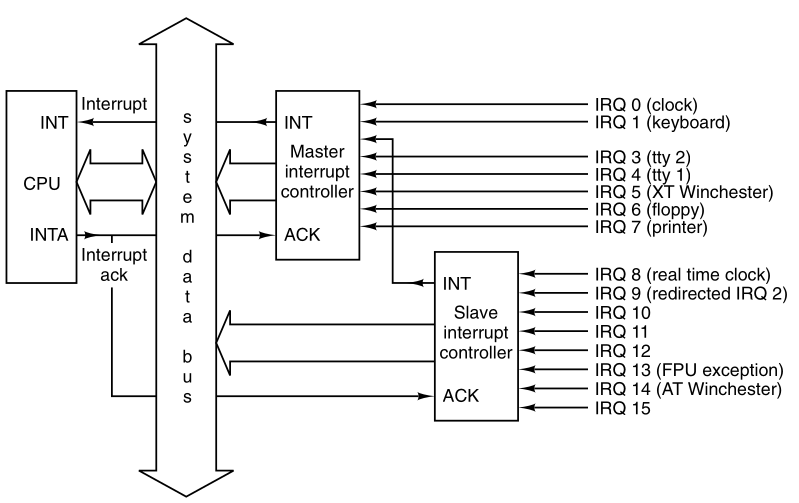
Interrupt processing hardware on a 32-bit Intel PC.
Some of the fifteen inputs are dedicated;
the clock input, IRQ 0, does not have a connection to any socket into
which a new adapter can be plugged.
Others are connected to physical sockets, and can be used for whatever
device is plugged in.
In the figure, interrupt signals arrive on the various IRQ n lines
shown at the right.
The connection to the CPU’s INT pin tells the processor that an
interrupt has occurred.
The INTA (interrupt acknowledge) signal from the CPU
signals the controller,
which responsible for the interrupt, to put data on the system data
bus,
telling the processor which service routine to execute.
The interrupt controller chips are programmed during system
initialization,
when main calls intr_init.
The programming determines the output sent to the CPU,
for a signal received on each of the input lines,
as well as various other parameters of the controller’s operation.
The data put on the bus is an 8-bit number,
used to index into a table of up to 256 elements.
The MINIX3 table has 56 elements.
Of these, 35 are actually used.
The others are reserved for use with future changes.
On 32-bit Intel processors this table contains interrupt gate
descriptors,
each of which is an 8-byte structure with several fields.
Several modes of response to interrupts are possible;
in the one used by MINIX3,
the fields of most concern to us in each of the interrupt gate
descriptors,
point to the service routine’s executable code segment,
and the starting address within it.
The CPU executes the code pointed to by the selected descriptor.
The result is exactly the same as execution of an:
int <nnn>
assembly language instruction.
The only difference is that in the case of a hardware
interrupt,
the <nnn> originates from a register in the interrupt
controller chip,
rather than from an instruction in program memory.
Interrupts cause a task-switching mechanism.
Changing the program counter (control register) to execute another
function is only a part of it.
When the CPU receives an interrupt while running a process,
it sets up a new stack for use during the interrupt service.
The location of this stack is determined by an entry in the Task State
Segment (TSS).
One such structure exists for the entire system,
initialized by cstart call to prot_init,
and modified as each process is started.
The new stack created by an interrupt always starts at the end of the
stackframe_s structure,
within the process table entry of the interrupted process.
The CPU automatically pushes several key registers onto this new
stack,
including those necessary to reinstate the interrupted process’ own
stack,
and restore its program counter.
When the interrupt handler code starts running,
it uses this area in the process table as its stack,
and much of the information needed to return to the interrupted process
will have already been stored.
The interrupt handler pushes the contents of additional registers,
filling the stackframe, and then switches to a stack provided by the
kernel,
while it does whatever must be done to service the interrupt.
Upon termination of an interrupt service routine,
the stack switches from the kernel stack back to another
stackframe,
which is in the process table,
(but not necessarily the same one that was created by the last
interrupt),
explicitly popping the additional registers,
and executing an iretd (return from interrupt)
instruction.
iretd restores the state that existed before an
interrupt,
restoring the registers that were pushed by the hardware,
and switching back to a stack that was in use before an interrupt.
Thus an interrupt stops a process,
and completion of the interrupt service restarts a process,
possibly a different one from the one that was most recently
stopped.
When a user process is interrupted,
nothing is stored on the interrupted process’ working stack.
Since the stack is created anew in a known location after an
interrupt,
control of multiple processes is simplified.
The location is determined by the TSS.
To start a different process,
with a pointer the stack pointer to the stackframe of another
process,
pop the registers that were explicitly pushed,
and execute an iretd instruction.
The CPU disables all interrupts when it receives an interrupt.
Thus, nothing can occur to cause the stackframe within a process table
entry to overflow.
This is automatic, but assembly-level instructions exist to disable and
enable interrupts, as well.
Interrupts remain disabled while the kernel stack,
located outside the process table, is in use.
A mechanism exists to allow an exception handler
to run when the kernel stack is in use
The exception handler is a response to an error detected by the
CPU.
An exception is similar to an interrupt,
and exceptions cannot be disabled.
Thus, for the sake of exceptions,
there must be a way to deal with what are essentially nested
interrupts.
In this case, a new stack is not created.
Instead, the CPU pushes the essential registers onto the existing
stack.
just those needed for resumption of the interrupted code.
An exception is not supposed to occur while the kernel is running,
however, and will result in a panic.
When an iretd is encountered while executing kernel
code,
the return mechanism is simpler than the one used when a user process is
interrupted.
The processor can determine how to handle the iretd,
by examining the code segment selector that is popped from the stack as
part of the iretd action.
The privilege levels mentioned earlier control the different
responses to interrupts.
They differ for those received while a process is running,
versus while kernel code is executing
(including interrupt service routines).
The simpler mechanism is used when the privilege levels are the
same.
That is, the level of the interrupted code is the same,
compared to the privilege level of the code to be executed in response
to the interrupt.
The usual case, however, is that the interrupted code is less privileged
than the interrupt service code,
and in this case, the more elaborate mechanism, using the TSS and a new
stack, is employed.
The privilege level of a code segment is recorded in the code segment
selector,
and as this is one of the items stacked during an interrupt,
it can be examined upon return from the interrupt to determine what the
iretd instruction must do.
The hardware checks to make sure the new stack is big enough,
for at least the minimum quantity of information that must be placed on
it.
This protects the more privileged kernel code from being accidentally
(or maliciously) crashed,
by a user process making a system call with an inadequate stack.
These mechanisms are built into the processor,
specifically for use in the implementation of operating systems that
support multiple processes.
This behavior may be confusing if you are unfamiliar with the
internal working of 32-bit Intel CPUs.
Ordinarily we try to avoid describing such details,
but understanding what happens when an interrupt occurs,
and when an iretd instruction is executed,
is essential to understanding how the kernel controls transitions,
to and from the “running” state.
The fact that the hardware handles much of the work,
makes life much easier for the programmer,
and presumably makes the resulting system more efficient.
All this help from the hardware does, however,
make it hard to understand what is happening just by reading the
software.
Having now described the interrupt mechanism,
we will return to mpx386.s and look at the tiny part of the
MINIX3 kernel that actually sees hardware interrupts.
An entry point exists for each interrupt.
The source code at each entry point, _hwint00 to
_hwint07, looks like a call to
hwint_master,
and the entry points _hwint08 to _hwint15 look
like calls to hwint_slave.
Each entry point appears to pass a parameter in the call,
indicating which device needs service.
In fact, these are really not calls, but macros,
and eight separate copies the macro definition of
hwint_master are assembled,
withonly the irq parameter different.
Similarly, eight copies of the hwint_slave macro are
assembled.
This may seem extravagant, but assembled code is very compact.
The object code for each expanded macro occupies fewer than 40
bytes.
In servicing an interrupt, speed is important,
and doing it this way eliminates the overhead,
of executing code to load a parameter,
call a subroutine, and retrieve the parameter.
We will continue the discussion of hwint_master as if it
really were a single function,
rather than a macro that is expanded in eight different places.
Recall that before hwint_master begins to execute,
the CPU has created a new stack in the stackframe_s of the
interrupted process,
within its process table slot.
Several key registers have already been saved there,
and all interrupts are disabled.
The first action of hwint_master is to call save.
This subroutine pushes all the other registers necessary to restart the
interrupted process.
Save could have been written inline as part of the macro to increase
speed,
but this would have more than doubled the size of the macro,
and in any case save is needed for calls by other functions.
As we shall see, save plays tricks with the stack.
Upon returning to hwint_master, the kernel stack is in
use,
not a stackframe in the process table.
Two tables declared in glo.h are now used.
_irq_handlers contains the hook information, including
addresses of handler routines.
The number of the interrupt being serviced is converted to an address
within _irq_handlers.
This address is then pushed onto the stack as the argument to
_intr_handle,
and _intr_handle is called.
We will look at the code of _intr_handle later.
Not only does it call the service routine for the interrupt that was
called,
it also sets or resets a flag in the _irq_actids
array,
to indicate whether this attempt to service the interrupt
succeeded,
and it gives other entries on the queue another chance to run and be
removed from the list.
Depending upon exactly what was required of the handler,
the IRQ may or may not be available to receive another interrupt,
upon the return from the call to _intr_handle.
This is determined by checking the corresponding entry in
_irq_actids.
A nonzero value in _irq_actids shows that interrupt
service for this IRQ is not complete.
If so, the interrupt controller is manipulated,
to prevent it from responding to another interrupt from the same IRQ
line.
This operation masks the ability of the controller chip to respond to a
particular input;
the CPU’s ability to respond to all interrupts is inhibited
internally,
when it first receives the interrupt signal,
and has not yet been restored at this point.
A few words about the assembly language code used may be helpful
,
to readers unfamiliar with assembly language programming.
The instruction:
jz 0f
does not specify a number of bytes to jump over.
The 0f is not a hexadecimal number, nor is it a normal label.
Ordinary label names are not permitted to begin with numeric
characters.
This is the way the MINIX3 assembler specifies a local label;
the 0f means a jump forward to the next numeric label 0.
The byte written allows the interrupt controller to resume normal
operation,
possibly with the line for the current interrupt disabled.
An interesting and possibly confusing point is that:
the 0: label occurs elsewhere in the same file, in
hwint_slave.
The situation is even more complicated than it looks at first
glance,
since these labels are within macros,
and the macros are expanded before the assembler sees this code.
Thus there are actually sixteen 0: labels in the code seen by the
assembler.
The possible proliferation of labels declared within macros,
is the reason why the assembly language provides local labels;
when resolving a local label,
the assembler uses the nearest one that matches in the specified
direction,
and additional occurrences of a local label are ignored.
_intr_handle is hardware dependent,
and details of its code will be discussed when we get to the file
i8259.c.
However, a few word about how it functions are in order now.
_intr_handle scans a linked list of structures that hold,
among other things,
addresses of functions to be called to handle an interrupt for a
device,
and the process numbers of the device drivers.
It is a linked list,
because a single IRQ line may be shared with several devices.
The handler for each device is supposed to test whether its device
actually needs service.
This step is not necessary for an IRQ such as the clock interrupt, IRQ
0,
which is hard wired to the chip that generates clock signals,
with no possibility of any other device triggering this IRQ.
The handler code is intended to be written so it can return
quickly.
If there is no work to be done,
or the interrupt service is completed immediately,
then the handler returns TRUE.
A handler may perform an operation like:
reading data from an input device,
and transferring the data to a buffer,
where it can be accessed,
when the corresponding driver has its next chance to run.
The handler may then cause a message to be sent to its device
driver,
which in turn causes the device driver to be scheduled to run as a
normal process.
If the work is not complete, the handler returns FALSE.
An element of the _irq_act_ids array is a bitmap,
that records the results for all the handlers on the list,
in such a way that the result will be zero, if and only if,
every one of the handlers returned TRUE.
If that is not the case,
then the code disables the IRQ,
before the interrupt controller as a whole is re-enabled.
This mechanism ensures that:
none of the handlers on the chain belonging to an IRQ will be
activated,
until all of the device drivers, to which these handlers belong,
have completed their work.
Obviously, there needs to be another way to re-enable an IRQ.
That is provided in a function enable_irq, which we will
see later.
Each device driver must be sure that enable_irq is called,
when its work is done.
It also is obvious that enable_irq first should reset its
own bit,
in the element of _irq_act_ids that corresponds to the IRQ
of the driver,
and then should test whether all bits have been reset.
Only then should the IRQ be re-enabled on the interrupt controller
chip.
What we have just described applies in its simplest form only to the
clock driver,
because the clock is the only interrupt-driven device that is compiled
into the kernel binary.
The address of an interrupt handler in another process is not meaningful
in the context of the kernel,
and the enable_irq function in the kernel cannot be called
by a separate process in its own memory space.
For user-space device drivers,
which means all device drivers that respond to hardware-initiated
interrupts,
except for the clock driver,
the address of a common handler, generic_handler,
is stored in the linked list of hooks.
The source code for this function is in the system task files,
but since the system task is compiled together with the kernel,
and since this code is executed in response to an interrupt,
it cannot really be considered part of the system task.
The other information, in each element of the list of hooks,
includes the process number of the associated device driver.
When generic_handler is called,
it sends a message to the correct device driver,
which causes the specific handler functions of the driver to run.
The system task supports the other end of the chain of events described
above as well.
When a user-space device driver completes its work,
it makes a sys_irqctl kernel call,
which causes the system task to call enable_irq,
on behalf of that driver to prepare for the next interrupt.
Returning our attention to hwint_master,
note that it terminates with a ret instruction.
It is not obvious that something tricky happens here.
If a process has been interrupted,
then the stack in use at this point is the kernel stack,
and not the stack within a process table,
that was set up by the hardware before hwint_master was
started.
In this case, manipulation of the stack by save,
will have left the address of _restart on the kernel
stack.
This results in a task, driver, server, or user process,
once again executing.
It may not be, and in fact very likely is not,
the same process as was executing when the interrupt occurred.
This depends upon whether the processing of the message,
created by the device-specific interrupt service routine,
caused a change in the process scheduling queues.
In the case of a hardware interrupt,
this will almost always be the case.
Interrupt handlers usually result in messages to device drivers,
and device drivers generally are queued on higher priority queues than
user processes.
This, then, is the heart of the mechanism which creates the illusion of
multiple processes executing simultaneously.
If an interrupt could occur while kernel code were executing,
then the kernel stack would already be in use,
and save would leave the address of restart1
on the kernel stack.
In this case, whatever the kernel was doing previously,
would continue after the ret at the end of
hwint_master.
This is a description of handling of nested interrupts,
and these are not allowed to occur in MINIX3;
interrupts are not enabled while kernel code is running.
However, as mentioned previously,
the mechanism is necessary in order to handle exceptions.
When all kernel routines involved in responding to an exception are
complete,
_restart will finally execute.
In response to an exception while executing kernel code,
it will almost certainly be true that a process different from the one
that was interrupted last will be put into execution.
The response to an exception in the kernel is a panic,
and what happens will be an attempt to shut down the system,
with as little damage as possible.
hwint_slave is similar to
hwint_master,
except that it must re-enable both the master and slave
controllers,
since both of them are disabled by receipt of an interrupt by the
slave.
Now let us move on to look at save, which we have
already mentioned.
Its name describes one of its functions,
which is to save the context of the interrupted process,
on the stack provided by the CPU,
which is a stackframe within the process table.
Save uses the variable _k_reenter,
to count and determine the level of nesting of interrupts.
If a process was executing when the current interrupt occurred,
the
mov esp, k_stktop
instruction switches to the kernel stack,
and the following instruction pushes the address of
_restart.
If an interrupt could occur while the kernel stack were already in
use,
then the address of restart1 would be pushed instead.
An interrupt is not allowed here,
but the mechanism is here to handle exceptions.
In either case, with a possibly different stack in use,
from the one that was in effect upon entry,
and with the return address in the routine that called it,
buried beneath the registers that have just been pushed,
an ordinary return instruction is not adequate for returning to the
caller.
The:
jmp RETADR-P_STACKBASE(eax)
instructions that terminate the two exit points of
save,
use the address that was pushed when save was called.
Reentrancy in the kernel causes many problems,
and eliminating it resulted in simplification of code in several
places.
In MINIX3 the _k_reenter variable still has a
purpose:
although ordinary interrupts cannot occur while kernel code is
executing,
exceptions are still possible.
For now, the thing to keep in mind is that:
the jump will never occur in normal operation.
It is, however, necessary for dealing with exceptions.
As an aside, we must admit that the elimination of reentrancy,
is a case where programming got ahead of documentation in the
development of MINIX3.
In some ways documentation is harder than programming;
the compiler or the program will eventually reveal errors in a
program.
There is no such mechanism to correct comments in source code.
There is a rather long comment at the start of
mpx386.s,
which is, unfortunately, incorrect.
The part of the comment should say that a kernel reentry can
occur,
only when an exception is detected.
System calls:
The next procedure in mpx386.s is
_s_call.
Before looking at its internal details, look at how it ends.
It does not end with a ret or jmp
instruction.
In fact, execution continues at_restart.
_s_call is the system call counterpart of the
interrupt-handling mechanism.
Control arrives at _s_call following a software
interrupt,
that is, execution of an int <nnn> instruction.
Software interrupts are treated like hardware interrupts,
except the index into the Interrupt Descriptor Table is encoded,
into the nnn part of an int <nnn>
instruction,
rather than being supplied by an interrupt controller chip.
Thus, when _s_call is entered,
the CPU has already switched to a stack inside the process table
(supplied by the Task State Segment),
and several registers have already been pushed onto this stack.
By falling through to _restart,
the call to _s_call ultimately terminates with an
iretd instruction,
and, just as with a hardware interrupt,
this instruction will start whatever process is pointed to by
proc_ptr at that point.
The image below compares the handling of a hardware interrupt,
and a system call using the software interrupt mechanism.
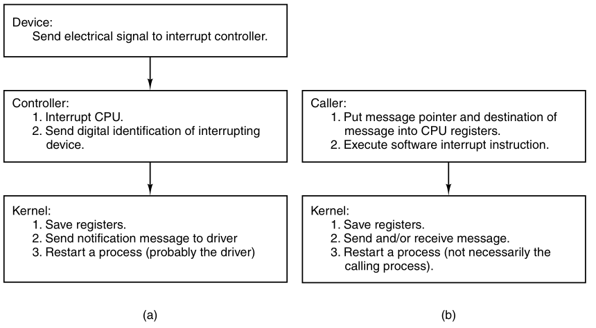
(a) How a hardware interrupt is processed.
(b) How a system call is made.
Let us now look at some details of _s_call.
The alternate label, _p_s_call,
is a vestige of the 16-bit version of MINIX3,
which has separate routines for protected mode and real mode
operation.
In the 32-bit version, all calls to either label, end up here.
A programmer invoking a MINIX3 system call,
writes a function call in C,
that looks like any other function call,
whether to a locally defined function,
or to a routine in the C library.
The library code supporting a system call:
sets up a message,
loads the address of the message and the process id of the destination
into CPU registers,
and then invokes an int SYS386_VECTOR instruction.
Control passes to the start of _s_call,
and several registers have already been pushed onto a stack inside the
process table.
All interrupts are disabled, too, as with a hardware interrupt.
The first part of the _s_call code resembles an inline
expansion of save,
and saves the additional registers that must be preserved.
Just as in save, the:
mov esp, k_stktop
instruction then switches to the kernel stack.
The similarity of a software interrupt to a hardware interrupt,
extends to both disabling all interrupts.
Following this comes a call to _sys_call,
which we will discuss in the next section.
It causes a message to be delivered,
and that this in turn, causes the scheduler to run.
Thus, when _sys_call returns,
it is probable that proc_ptr will be pointing to a
different process,
from the one that initiated the system call.
Then execution falls through to restart.
We have seen that _restart is reached in several
ways:
hwint_master or hwint_slave
after a hardware interrupt._s_call after a system
call.The figure below is a simplified summary,
of how control passes back and forth between processes and the kernel
via_restart:
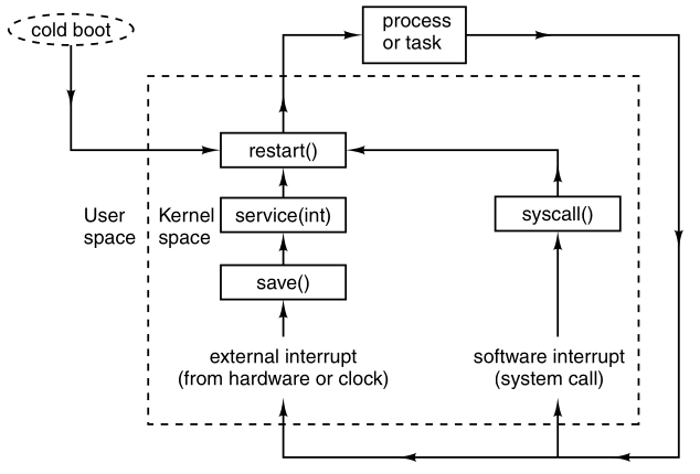
_restart is the common point reached after either:
system startup, interrupts, or system calls.
The most deserving process, which may be, and often is,
a different process from the last one interrupted, runs next.
Interrupts that occur while the kernel itself is running,
are not shown in this diagram,
In every case, interrupts are disabled when _restart is
reached.
The next process to run has been definitively chosen,
and with interrupts disabled, it cannot be changed.
The process table was carefully constructed,
so it begins with a stack frame,
and the instruction on this line,
mov esp, (_proc_ptr)
points the CPU’s stack pointer register at the stack frame.
The instruction:
lldt P_LDT_SEL(esp)
loads the processor’s local descriptor table register from the stack
frame.
This prepares the processor to use the next memory segments,
belonging to the next process to be run.
The following instruction sets an address,
in the next process’ process table entry,
to that where the stack for the next interrupt will be set up,
and the following instruction stores this address into the Task State
Segment (TSS).
The first part of _restart would not be necessary,
if an interrupt occurred when kernel code were executing,
since the kernel stack would be in use,
and termination of the interrupt service would allow the kernel code to
continue.
The same applies for interrupt service code.
But, in fact, the kernel is not reentrant in MINIX3,
and ordinary interrupts cannot occur this way.
Disabling interrupts does not disable the ability of the processor to
detect exceptions.
If an exception occurs while executing kernel code (something we hope
will never happen),
the label restart1 marks the point where execution would
resume.
At this point k_reenter is decremented, to record
that:
one level of possibly nested interrupts has been disposed of,
and the remaining instructions restore the process,
to the state it was in when the next process executed last.
The penultimate instruction modifies the stack pointer,
so that the return address that was pushed,
when save was called, is ignored.
If the last interrupt occurred when a process was executing,
then the final instruction, iretd,
completes the return to execution,
of whatever process is being allowed to run next,
restoring its remaining registers,
including its stack segment and stack pointer.
If, however, this encounter with the iretd came via
restart1,
the kernel stack in use is not a stackframe, but the kernel stack,
and this is not a return to an interrupted process,
but the completion of handling an exception that occurred while kernel
code was executing.
The CPU detects this,
when the code segment descriptor is popped from the stack,
during execution of the iretd,
and the complete action of the iretd, in this case,
is to retain the kernel stack in use.
Exceptions:
Now it is time to say something more about exceptions.
An exception is caused by various error conditions internal to the
CPU.
Exceptions are not always bad.
They can be used to ask the operating system to provide a
service,
such as providing more memory for a process to use,
or swapping in a currently swapped-out memory page,
although such services are not implemented in MINIX3.
They also can be caused by programming errors:
Within the kernel an exception is very serious,
and grounds to panic.
When an exception occurs in a user program,
the program may need to be terminated,
but the operating system should be able to continue.
Exceptions are handled by the same mechanism as interrupts,
using descriptors in the interrupt descriptor table.
These entries in the table,
point to the sixteen exception handler entry points,
beginning with _divide_error and ending with
_copr_error,
found near the end of mpx386.s.
These all jump to exception or
errexception,
depending upon whether:
the condition pushes an error code onto the stack, or not.
The handling here in the assembly code is similar to what we have
already seen,
registers are pushed, and the C routine _exception,
from /kernel/exception.c.
(note the underscore) is called to handle the event.
The consequences of exceptions vary.
Some are ignored, some cause panics,
and some result in sending signals to processes.
We will examine _exception in a later section.
One other entry point to the mpx386.s file,
is handled like an interrupt: _level0_call.
It is used when code must be run with privilege level 0,
the most privileged level.
The entry point is here in mpx386.s,
with the interrupt and exception entry points,
because it too is invoked by execution of an
int <nnn> instruction.
Like the exception routines, it calls save,
and thus the code that is jumped to, eventually will terminate,
with a ret that leads to _restart.
Its usage will be described in a later section,
when we encounter some code that needs privileges normally not
available,
even to the kernel.
Finally, at the end of the assembly language file,
some data storage space is reserved.
Two different data segments are defined here.
.sect .rom
this declaration allocates storage space at the beginning of the
kernel’s data segment,
and does so at the start of a read-only section of memory.
The compiler puts a magic number here,
so boot can verify that the file it loads is a valid kernel image.
When compiling the complete system,
various string constants will be stored following this.
The other data storage area defined at the:
.sect .bss
declaration reserves space in the kernel’s normal uninitialized variable
area,
for the kernel stack, and above that,
some space is reserved for variables used by the exception
handlers.
Servers and ordinary processes have stack space reserved,
when an executable file is linked,
and depend upon the kernel to properly set the stack segment
descriptor,
and the stack pointer, when they are executed.
The kernel has to do this for itself.
Processes in MINIX3 communicate by messages,
using the rendezvous principle.
Send
When a process does a send,
the lowest layer of the kernel performs a check,
to see if the destination is waiting for a message from the sender (or
from ANY sender).
If so, then the message is copied,
from the sender’s buffer to the receiver’s buffer,
and both processes are marked as runnable.
If the destination is not waiting for a message from the
sender,
then the sender is marked as blocked,
and put onto a queue of processes waiting to send to the receiver.
Receive
When a process does a receive,
the kernel checks to see if any process is queued trying to send to
it.
If so, the message is copied from the blocked sender to the
receiver,
and both are marked as runnable.
If no process is queued trying to send to it,
the receiver blocks, until a message arrives.
Notify
In MINIX3, components of the operating system run as totally separate
processes,
Sometimes the rendezvous method is not quite enough for the OS.
The notify primitive is provided for precisely these
occasions.
A notify sends a bare-bones message.
If the destination is not waiting for a message,
then the sender is not blocked
The notify is not lost, however.
The next time the destination does a receive,
pending notifications are delivered, before ordinary messages.
Notifications can be used in situations where using ordinary messages
could cause deadlocks.
Earlier we pointed out a deadlock situation:
where process A blocks, sending a message to process B,
and process B blocks, sending a message to process A.
If one of the messages is a non-blocking notification,
then there is no problem.
In most cases, a notification informs the recipient of its origin,
and little more.
Sometimes that is all that is needed,
but there are two special cases,
where a notification conveys some additional information.
The receiving destination process can send a message,
to the source of the notification,
to request more information.
The high-level code for interprocess communication is found in
proc.c.
The kernel’s job is to translate,
either a hardware interrupt, or a software interrupt, into a
message.
Hardware interrupts are generated by hardware.
Software interrupts are the way a request for system services,
that is, a system call, is communicated to the kernel.
These cases are similar enough,
that they could have been handled by a single function,
but it was more efficient to create specialized functions.
One comment and two macro definitions near the beginning of this file
deserve mention.
For manipulating lists, pointers to pointers are used extensively,
and a comment explains their advantages and use.
Two useful macros for messages are defined:
One macro, CopyMess, short for copy message,
is a programmer-friendly interface,
to the assembly language routine cp_mess in
klib386.s.
It is used for copying both full and notification messages.
BuildMess, although its “build message” name implies
more generality,
is only used for constructing the messages used by
notify.
The only function call is to get_uptime,
which reads a variable maintained by the clock task,
so the notification can include a timestamp.
The apparent calls to a function named priv,
are actually expansions of another macro,
defined in priv.h,
#define priv(rp) ((rp)->p_priv)
The priv macro is used for two special cases:
If the origin of a notification is HARDWARE,
then it carries a payload,
a copy of the destination process’ bitmap of pending interrupts.
If the origin is SYSTEM,
then the payload is the bitmap of pending signals.
Because these bitmaps are available,
in the priv table slot of the destination process,
they can be accessed at any time.
Notifications can be delivered later,
if the destination process is not blocked,
waiting for them, at the time they are sent.
For ordinary messages, this would require some kind of buffer,
in which an undelivered message could be stored.
To store a notification, all that is required is a bitmap,
in which each bit corresponds to a process,
that can send a notification.
When a notification cannot be sent,
the bit corresponding to the sender is set,
in the recipient’s bitmap.
When a receive is done, the bitmap is checked,
and if a bit is found to have been set,
then the message is regenerated.
The bit tells the origin of the message,
and if the origin is HARDWARE or SYSTEM,
the additional content is added.
The only other item needed is the timestamp,
which is added when the message is regenerated.
For the purposes for which they are used,
timestamps do not need to show when a notification was first
attempted;
the time of delivery is sufficient.
sys_callThe first function in proc.c is
sys_call.
It converts a software interrupt into a message.
The int SYS386_VECTOR instruction,
by which a system call is initiated,
is converted into a message.
There are a wide range of possible sources and destinations,
and the call may require either:
sending or receiving a message,
or both sending and receiving a message.
First, the function code, SEND, RECEIVE,
etc., and the flags,
are extracted from the first argument of the call.
Then, a number of tests must be made:
The first test is to see if the calling process is allowed to make
the call.
iskerneln, is a macro defined in proc.h.
The next test is to see that the specified source or destination is a valid process.
Then a check is made that the message pointer points to a valid area of memory.
MINIX3 privileges define which other processes any given process is
allowed to send to,
and this is tested next.
Finally, a test is made to verify that the destination process is
running,
and has not initiated a shutdown.
After all the tests have been passed,
one of the functions mini_send, mini_receive,
or mini_notify,
is called to do the real work.
If the function was ECHO,
then the CopyMess macro is used,
with identical source and destination.
ECHO is meant only for testing, as mentioned earlier.
The errors tested for in sys_call are unlikely,
but the tests are easily done,
since ultimately they compile into code to perform comparisons of small
integers.
At this most basic level of the operating system,
testing for even the most unlikely errors is advisable.
This code is likely to be executed many times each second,
during every second that the computer system on,
which it runs is active.
The functions mini_send, mini_rec, and
mini_notify
are the heart of the normal message passing mechanism of MINIX3,
and deserve careful study.
mini_sendmini_send has the parameters:
the caller,
the process to be sent to,
and a pointer to the buffer where the message is.
After all the tests performed by sys_call,
another is necessary,
which is to detect a send deadlock.
The test verifies that the caller and destination are not trying to send
to each other.
Now, a check is made:
to see if the destination is blocked on a receive,
as shown by the RECEIVING bit, in the
p_rts_flags field,
of its process table entry.
If it is waiting, then the next question is:
“Who is it waiting for?”
If it is waiting for the sender, or for ANY,
the CopyMess macro is used to copy the message,
and the receiver is unblocked,
by resetting its RECEIVING bit.
Then enqueue is called,
to give the receiver an opportunity to run.
If, on the other hand, the receiver is not blocked,
or is blocked but waiting for a message from someone else,
then the code is executed to block and dequeue the
sender.
All processes wanting to send to a given destination,
are strung together on a linked list,
with the destination’s p_callerq field,
pointing to a process table entry,
of the process at the head of the queue.
In the image below,
(a) shows what happens when process 3 is unable to send to process
0.
(b) If process 4 is subsequently also unable to send to process 0.
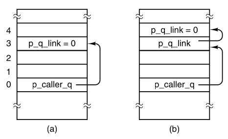
Queueing of processes trying to send to process 0.
mini_receiveWhen sys_call has function argument is
RECEIVE or BOTH,
mini_receive is called.
It receives both full and notification messages.
Notifications have a higher priority than ordinary messages.
However, a notification will never be the right reply to a
send,
so only if the SENDREC_BUSY flag is not set,
are the bitmaps checked,
to see if there are pending notifications.
If a notification is found,
then it is marked as no longer pending, and delivered.
Delivery uses both the BuildMess and CopyMess
macros,
defined near the top of proc.c.
One might have thought that,
because a timestamp is part of a notify message,
it would convey useful information.
For example, if the recipient had been unable to do a receive for a
while,
the timestamp would tell how long it had been undelivered.
But the notification message is generated (and timestamped),
at the time it is delivered, not at the time it was sent.
There is a purpose behind constructing the notification messages at the
time of delivery.
All that is necessary is to set a bit,
to remember that, when delivery becomes possible,
a notification should be generated.
This is efficient, one bit per pending notification.
It is also the case that,
the current time is usually what is needed.
For example,
notification is used to deliver a SYN_ALARM message to the
process manager,
and if the timestamp were not generated when the message was
delivered,
then the PM would need to ask the kernel for the correct
time,
before checking its timer queue.
Note that only one notification is delivered at a time,
mini_send returns after delivery of a notification.
However, the caller is not blocked,
so it is free to do another receive,
immediately after getting the notification.
If there are no notifications,
then the caller queues are checked,
to see if a message of any other type is pending.
If such a message is found,
then it is delivered by the CopyMess macro,
and the originator of the message is then unblocked,
by the call to enqueue.
The caller is not blocked in this case.
If no notifications or other messages were available,
then the caller will be blocked, by the call to dequeue.
mini_notifymini_notify is used to effectuate a notification.
It is similar to mini_send,
and can be discussed quickly.
If the recipient of a message is blocked and waiting to
receive,
then the notification is generated by BuildMess and
delivered.
Also, the recipient’s RECEIVING flag is turned off,
and then it is enqueue-ed.
If the recipient is not waiting,
then a bit is set in its s_notify_pending map,
which indicates that a notification is pending,
and identifies the sender.
The sender then continues its own work,
and if another notification to the same recipient is needed,
before an earlier one has been received,
then the bit in the recipient’s bitmap is overwritten;
effectively, multiple notifications from the same sender are
merged,
into a single notification message.
This design eliminates the need for buffer management,
while offering asynchronous message passing.
When mini_notify is called because of a software
interrupt,
and a subsequent call to sys_call,
interrupts will be disabled at the time.
But the clock or system task,
or some other task that might be added to MINIX3 in the future,
might need to send a notification at a time when interrupts are not
disabled.
lock_notify is a safe gateway to
mini_notify.
It checks k_reenter to see if interrupts are already
disabled,
and if they are, it just calls mini_notify right
away.
If interrupts are enabled, then:
they are disabled, by a call to lock,
mini_notify is called,
and then interrupts are re-enabled, by a call to unlock.
MINIX3 uses a multilevel scheduling algorithm.
Processes are given initial priorities that are related to their
layer,
There are more than the initial layers,
and the priority of a process may change during its execution.
The clock and system tasks in layer 1 receive the highest
priority.
The device drivers of layer 2 get lower priority,
but they are not all equal.
Server processes in layer 3 get lower priorities than drivers,
but some less than others.
User processes start with less priority than any of the system
processes,
and initially are all equal,
though the nice command can raise or lower the priority of
a user process.
The scheduler maintains 16 queues of runnable processes,
although not all of them may be used at a particular moment.
The image shows the linked-list queues,
and the processes that are in place,
at the instant the kernel completes initialization and begins to
run,
that is, at the call to restart in main.c.
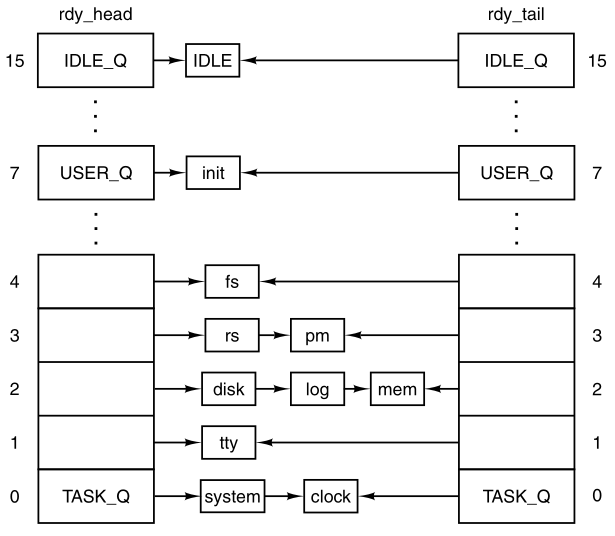
The scheduler maintains sixteen queues, one per priority level.
Shown here is the initial queuing of processes as MINIX3 starts up.
The array rdy_head has one entry for each queue,
with that entry pointing to the process at the head of the queue.
Similarly, rdy_tail is an array,
whose entries point to the last process on each queue.
Both of these arrays are defined with the EXTERN macro
in proc.h.
The initial queueing of processes during system startup,
is determined by the image table in table.c.
Scheduling is round robin in each queue.
If a running process uses up its quantum,
then it is moved to the tail of its queue,
and given a new quantum.
However, when a blocked process is awakened,
if it had any part of its quantum left, when it blocked,
then it is put at the head of its queue.
It is not given a complete new quantum, however;
it gets only what it had left when it blocked.
The array rdy_tail makes adding a process to the end of
a queue efficient.
Whenever a running process becomes blocked,
or a runnable process is killed by a signal,
that process is removed from the scheduler’s queues.
Only runnable processes are queued.
Given the queue structures just described,
the scheduling algorithm is simple:
find the highest priority queue, that is not empty,
and pick the process at the head of that queue.
The IDLE process is always ready,
and is in the lowest priority queue.
If all the higher priority queues are empty,
then IDLE is run.
We saw a number of references to enqueue and dequeue in the last section.
‘enqueue’ is called with a pointer to a process table entry as its
argument.
It calls another function, sched,
with pointers to variables that determine which queue the process should
be on,
and whether it is to be added to the head or the tail of that queue.
Now there are three possibilities.
These are classic data structures examples:
empty
If the chosen queue is empty,
then both rdy_head and rdy_tail are made to
point to the process being added,
and the link field, p_nextready,
gets the special pointer value that indicates nothing follows,
NIL_PROC.
head
If the process is being added to the head of a queue,
then its p_nextready gets the current value of
rdy_head,
and then rdy_head is pointed to the new process.
tail
If the process is being added to the tail of a queue,
then the p_nextready of the current occupant of the
tail,
is pointed to the new process, as is rdy_tail.
The p_nextready of the newly-ready process then is pointed
to NIL_PROC.
Finally, pick_proc is called to determine which process
will run next.
When a process must be made unready,
then dequeue is called.
A process must be running in order to block,
so the process to be removed is likely to be at the head of its
queue.
However, a signal could have been sent to a process that was not
running.
So the queue is traversed to find the target,
with a high likelihood it will be found at the head.
When it is found,
all pointers are adjusted appropriately,
to take it out of the chain.
If it was running,
then pick_proc must also be called.
One other point of interest is found in this function.
Because tasks that run in the kernel share a common hardware-defined
stack area,
it is a good idea to check the integrity of their stack areas
occasionally.
At the beginning of dequeue, a test is made,
to see if the process being removed from the queue,
is one that operates in kernel space.
If it is, a check is made, to see that:
the distinctive pattern written at the end of its stack area,
has not been overwritten.
Now we come to sched,
which picks which queue to put a newly-ready process on,
and whether to put it on the head or the tail of that queue.
Recorded in the process table for each process are:
its quantum, the time left on its quantum,
its priority, and the maximum priority it is allowed.
A check is made to see if the entire quantum was used.
If not, it will be restarted,
with whatever it had left from its last turn.
If the quantum was used up, then a check is made,
to see if the process had two turns in a row,
with no other process having run.
This is taken as a sign of a possible infinite,
or at least, excessively long, loop,
and a penalty of +1 is assigned.
However, if the entire quantum was used,
but other processes have had a chance to run,
then the penalty value becomes −1.
This does not help if two or more processes are executing in a loop
together.
How to detect that is an open problem.
Next, the queue to use is determined.
Queue 0 is highest priority; queue 15 is lowest.
One could argue it should be the other way around,
but this way is consistent with the traditional “nice” values used by
UNIX,
where a positive “nice” means a process runs with lower priority.
Kernel processes (the clock and system tasks) are immune,
but all other processes may have their priority reduced, that is,
be moved to a higher-numbered queue,
by adding a positive penalty.
All processes start with their maximum priority,
so a negative penalty does not change anything,
until positive penalties have been assigned.
There is also a lower bound on priority,
ordinary processes never can be put on the same queue as IDLE.
pick_procNow we come to pick_proc.
This function’s major job is to set next_ptr.
Any change to the queues, that might affect the choice of which process
to run next,
requires pick_proc to be called again.
Whenever the current process blocks,
pick_proc is called to reschedule the CPU.
In essence, pick_proc is the scheduler.
pick_proc is simple.
Each queue is tested.
TASK_Q is tested first, and if a process on this queue is
ready,
then pick_proc sets proc_ptr, and returns
immediately.
Otherwise, the next lower priority queue is tested, all the way down to
IDLE_Q.
The pointer bill_ptr is changed to charge the user process
for the CPU time it is about to be given.
This assures that the last user process to run is charged for work done
on its behalf by the system.
The remaining procedures in proc.c are:
lock_send, lock_enqueue, and
lock_dequeue.
These all provide access to their basic functions using lock and
unlock,
in the same way we discussed for lock_notify.
In summary, the scheduling algorithm maintains multiple priority
queues.
The first process on the highest priority queue is always run
next.
The clock task monitors the time used by all processes.
If a user process uses up its quantum,
then it is put at the end of its queue,
thus achieving a simple round-robin scheduling,
among the competing user processes.
Tasks, drivers, and servers are expected to run until they block,
and are given large quanta,
but if they run too long,
then they may also be preempted.
This is not expected to happen very often,
but it is a mechanism to prevent a high-priority process that has a
problem,
from locking up the system.
A process that prevents other processes from running,
may also be moved to a lower priority queue temporarily.
Several functions written in C are nevertheless hardware
specific.
To facilitate porting MINIX3 to other systems,
these functions are segregated in the files to be discussed in this
section,
exception.c, i8259.c, and
protect.c,
rather than being included in the same files with the higher-level code
they support.
exception.c contains the exception handler,
exception, which is called (as _exception)
by the assembly language part of the exception handling code in
mpx386.s.
Exceptions that originate from user processes are converted to
signals.
Users are expected to make mistakes in their own programs,
but an exception originating in the operating system,
indicates something is seriously wrong and causes a panic.
The array ex_data determines the error message to be
printed in case of panic,
or the signal to be sent to a user process, for each exception.
Earlier Intel processors do not generate all the exceptions,
and the third field in each entry indicates the minimum processor model
that is capable of generating each one.
This array provides an interesting summary of the evolution of the Intel
family of processors,
upon which MINIX3 has been implemented.
If a panic results from an interrupt that would not be expected from the
processor in use,
then an alternate message is printed.
Hardware-Dependent Interrupt Support
The three functions in i8259.c are used during system
initialization,
to initialize the Intel 8259 interrupt controller chips.
The macro defines a dummy function
(the real one is needed only when MINIX3 is compiled for a 16bit Intel
platform).
intr_init initializes the controllers.
Two steps ensure that no interrupts will occur before all the
initialization is complete.
First intr_disable is called.
This is a C language call to an assembly language function in the
library,
that executes a single instruction, cli,
which disables the CPU’s response to interrupts.
Then a sequence of bytes is written to registers on each interrupt
controller,
the effect of which is to inhibit response of the controllers to
external input.
The byte written is all ones,
except for a zero at the bit that controls the cascade input,
from the slave controller to the master controller
(Recall the diagram of hardware interrupt wiring).
A zero enables an input, a one disables.
The byte written to the secondary controller is all ones.
A table stored in the i8259 interrupt controller chip generates an
8-bit index,
that the CPU uses to find the correct interrupt gate descriptor for each
possible interrupt input
(the signals on the right-hand side of the interrupt wiring diagram
above).
This is initialized by the BIOS when the computer starts up,
and these values can almost all be left in place.
As drivers that need interrupts start up,
changes can be made where necessary.
Each driver can then request that a bit be reset in the interrupt
controller chip,
to enable its own interrupt input.
The argument mine to intr_init,
is used to determine whether MINIX3 is starting up or shutting
down.
This function can be used, both to initialize at startup,
and to restore the BIOS settings when MINIX3 shuts down.
After initialization of the hardware is complete,
the last step in intr_init is to copy the BIOS interrupt
vectors to the MINIX3 vector table.
The second function in i8259.c is
put_irq_handler.
At initialization put_irq_handler is called for each
process that must respond to an interrupt.
This puts the address of the handler routine into the interrupt
table,
irq_handlers, defined as EXTERN in
glo.h.
With modern computers 15 interrupt lines is not always enough
(because there may be more than 15 I/O devices)
so two I/O devices may need to share an interrupt line.
This will not occur with any of the basic devices supported by MINIX3 as
described in this text,
but when network interfaces, sound cards, or more esoteric I/O devices
must be supported,
they may need to share interrupt lines.
To allow for this, the interrupt table is not just a table of
addresses.
irq_handlers[NR_IRQ_VECTORS] is an array of pointers to
irq_hook structs,
a type defined in kernel/type.h.
These structures contain a field, which is a pointer to another
structure of the same type,
so a linked list can be built, starting with one of the elements of
irq_handlers.
put_irq_handler adds an entry to one of these lists.
The most important element of such an entry is a pointer to an interrupt
handler,
the function to be executed when an interrupt is generated,
for example, when requested I/O has completed.
Some details of put_irq_handler deserve mention.
Note the variable id which is set to 1,
just before the beginning of the while loop that scans through the
linked list.
Each time through the loop id is shifted left 1 bit.
The test limits the length of the chain to the size of id,
or 32 handlers for a 32-bit system.
In the normal case, the scan will result in finding the end of the
chain,
where a new handler can be linked.
When this is done, id is also stored in the field of the
same name,
in the new item on the chain.
put_irq_handler also sets a bit in the global variable
irq_use,
to record that a handler exists for this IRQ.
If you understand the MINIX3 design goal of putting device drivers in
user-space,
the preceding discussion of how interrupt handlers are called,
will have left you slightly confused.
The interrupt handler addresses stored in the hook structures,
cannot be useful unless they point to functions within the kernel’s
address space.
The only interrupt-driven device in the kernel’s address space is the
clock.
What about device drivers that have their own address spaces?
The answer is, the system task handles it.
That is true for most communication between the kernel and processes in
userspace.
A user space device driver that is to be interrupt-driven,
when it needs to register as an interrupt handler,
makes a sys_irqctl call to the system task.
The system task then calls put_irq_handler,
but instead of the address of an interrupt handler in the driver’s
address space,
the address of generic_handler, part of the system
task,
is stored in the interrupt handler field.
The process number field in the hook structure is used by
generic_handler,
to locate the priv table entry for the driver,
and the bit in the driver’s pending interrupts bitmap corresponding to
the interrupt is set.
Then generic_handler sends a notification to the
driver.
The notification is identified as being from HARDWARE,
and the pending interrupts bitmap for the driver is included in the
message.
Thus, if a driver must respond to interrupts from more than one
source,
then it can learn which one is responsible for the current
notification.
In fact, since the bitmap is sent,
one notification provides information on all pending interrupts for the
driver.
Another field in the hook structure is a policy field,
which determines whether the interrupt is to be re-enabled
immediately,
or whether it should remain disabled.
In the latter case, it will be up to the driver to make a
sys_irqenable kernel call,
when service of the current interrupt is complete.
One of the goals of MINIX3 design is to support run-time
reconfiguration of I/O devices.
The next function, rm_irq_handler, removes a handler,
a necessary step if a device driver is to be removed, and possibly
replaced by another.
Its action is just the opposite of put_irq_handler.
The last function in this file, intr_handle,
is called from the hwint_master and
hwint_slave macros we saw in mpx386.s.
The element of the array of bitmaps irq_actids which
corresponds the interrupt being serviced is used to keep track of the
current status of each handler in a list.
For each function in the list, intr_handle sets the
corresponding bit in irq_actids, and calls the
handler.
If a handler has nothing to do or if it completes its work
immediately,
then it returns “true” and the corresponding bit in
irq_actids is cleared.
The entire bitmap for an interrupt, considered as an integer,
is tested near the end of the hwint_master and
hwint_slave macros,
to determine if that interrupt can be re-enabled before another process
is restarted.
Intel Protected Mode Support.
protect.c contains routines related to protected mode
operation of Intel processors.
The Global Descriptor Table (GDT), Local Descriptor Tables (LDTs), and
the Interrupt Descriptor Table,
all located in memory, provide protected access to system
resources.
The GDT and IDT are pointed to by special registers within the
CPU,
and GDT entries point to LDTs.
The GDT is available to all processes,
and holds segment descriptors for memory regions used by the operating
system.
Normally, there is one LDT for each process,
holding segment descriptors for the memory regions used by the
process.
Descriptors are 8-byte structures with a number of components,
but the most important parts of a segment descriptor,
are the fields that describe the base address and the limit of a memory
region.
The IDT is also composed of 8-byte descriptors,
with the most important part being the address of the code to be
executed,
when the corresponding interrupt is activated.
cstart in start.c calls
prot_init, which sets up the GDT.
The IBM PC BIOS requires that it be ordered in a certain way,
and all the indices into it are defined in protect.h.
Space for an LDT for each process is allocated in the process
table.
Each contains two descriptors, for a code segment and a data
segment.
Recall we are discussing here segments as defined by the hardware;
these are not the same as the segments managed by the operating
system,
which considers the hardware-defined data segment to be further
divided,
into data and stack segments.
Descriptors for each LDT are built in the GDT.
The functions init_dataseg and init_codeseg
build these descriptors.
The entries in the LDTs themselves are initialized when a process’
memory map is changed
(i.e., when an exec system call is made).
Another processor data structure that needs initialization is the
Task State Segment (TSS).
The structure is defined at the start of this file,
and provides space for storage of processor registers,
and other information that must be saved when a task switch is
made.
MINIX3 uses only the fields that define where a new stack is to be built
when an interrupt occurs.
The call to init_dataseg ensures that it can be located
using the GDT.
To understand how MINIX3 works at the lowest level,
perhaps the most important thing is to understand how:
exceptions, hardware interrupts, or int <nnn>
instructions,
lead to the execution of the various pieces of code,
that has been written to service them.
These events are processed by means of the interrupt gate descriptor
table.
The array gate_table, is initialized by the compiler,
with the addresses of the routines that handle exceptions and hardware
interrupts,
and then is used in the loop to initialize this table,
using calls to the int_gate function.
There are good reasons for the way the data are structured in the
descriptors,
based on details of the hardware, and the need to maintain
compatibility,
between advanced processors and the 16-bit 286 processor.
Fortunately, we can usually leave these details to Intel’s processor
designers.
For the most part, the C language allows us to avoid the details.
However, in implementing a real operating system the details must be
faced at some point.
The image shows the internal structure of one kind of segment
descriptor:
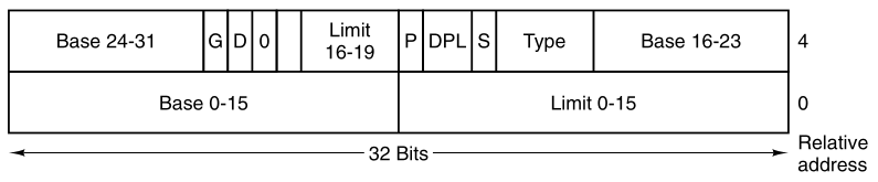
The format of an Intel segment descriptor.
Note that the base address,
which C programs can refer to as a simple 32-bit unsigned integer,
is split into three parts,
two of which are separated by a number of 1-, 2-, and 4-bit
quantities.
The limit is a 20-bit quantity stored as separate 16-bit and 4-bit
chunks.
The limit is interpreted as either a number of bytes or a number of
4096-byte pages,
based on the value of the G (granularity) bit.
Other descriptors, such as those used to specify how interrupts are
handled,
have different, but equally complex structures.
We discuss these structures in more detail later.
Most of the other functions defined in protect.c,
are devoted to converting between variables used in C programs,
and the rather ugly forms these data take in the machine readable
descriptors,
such as the one immediately above.
init_codeseg and init_dataseg are similar
in operation,
and are used to convert the parameters passed to them into segment
descriptors.
They each, in turn, call the next function, sdesc, to
complete the job.
This is where the messy details of the structure shown above are dealt
with.
init_codeseg and init_data_seg are not used
just at system initialization.
They are also called by the system task whenever a new process is
started up, in order to allocate the proper memory segments for the
process to use.
seg2phys, called only from start.c,
performs an operation which is the inverse of that of
sdesc, extracting the base address of a segment from a
segment descriptor.
phys2seg, is no longer needed, the
sys_segctl kernel call now handles access to remote memory
segments, for example, memory in the PC’s reserved area between 640K and
1M.
int_gate performs a similar function to
init_codeseg and init_dataseg in building
entries for the interrupt descriptor table.
Now we come to a function in protect.c,
enable_iop, that can perform a dirty trick.
It changes the privilege level for I/O operations,
allowing the current process to execute instructions which read and
write I/O ports.
The description of the purpose of the function is more complicated than
the function itself,
which just sets two bits in the word in the stack frame entry of the
calling process,
that will be loaded into the CPU status register, when the process is
next executed.
A function to undo this is not needed,
as it will apply only to the calling process.
This function is not currently used,
and no method is provided for a user space function to activate it.
The final function in protect.c is
alloc_segments.
It is called by do_newmap.
It is also called by the main routine of the kernel during
initialization.
This definition is very hardware dependent.
It takes the segment assignments that are recorded in a process table
entry,
and manipulates the registers and descriptors the Pentium processor
uses,
to support protected segments at the hardware level.
Multiple assignments are a feature of the C language.
Finally, the kernel has a library of support functions,
written in assembly language, that are included by compiling
klib.s,
and a few utility programs, written in C, in the file
misc.c.
Let us first look at the assembly language files.
klib.s is a short file, similar to
mpx.s,
which selects the appropriate machine-specific version,
based upon the definition of WORD_SIZE.
The code we will discuss is in klib386.s.
This contains about two dozen utility routines that are in assembly
code,
either for efficiency or because they cannot be written in C at all.
_monitor makes it possible to return to the boot
monitor.
From the point of view of the boot monitor, all of MINIX3 is just a
subroutine,
and when MINIX3 is started, a return address to the monitor is left on
the monitor’s stack.
_monitor just has to restore the various segment
selectors,
and the stack pointer that was saved when MINIX3 was started,
and then return as from any other subroutine.
Int86 supports BIOS calls.
The BIOS is used to provide alternative disk drivers which are not
described here.
Int86 transfers control to the boot monitor,
which manages a transfer from protected mode to real mode to execute a
BIOS call,
then back to protected mode for the return to 32-bit MINIX3.
The boot monitor also returns the number of clock ticks counted during
the BIOS call.
How this is used will be seen in the discussion of the clock task.
Although _phys_copy (see below) could have been used for
copying messages,
_cp_mess, a faster specialized procedure, has been provided
for that purpose.
It is called by:
cp_mess(source, src_clicks, src_offset, dest_clicks, dest_offset);
where source is the sender’s process number,
which is copied into the m_source field of the receiver’s
buffer.
Both the source and destination addresses are specified,
by giving a click number, typically the base of the segment containing
the buffer,
and an offset from that click.
This form of specifying the source and destination,
is more efficient than the 32-bit addresses used by
_phys_copy.
_Exit, __exit, and ___exit are
defined,
because some library routines that might be used in compiling
MINIX3,
make calls to the standard C function exit.
An exit from the kernel is not a meaningful concept;
there is nowhere to go.
Consequently, the standard exit cannot be used here.
The solution here is to enable interrupts and enter an endless
loop.
Eventually, an I/O operation, or the clock, will cause an
interrupt,
and normal system operation will resume.
The entry point for ___main is another attempt to deal with
a compiler action which,
while it might make sense while compiling a user program, d
oes not have any purpose in the kernel.
It points to an assembly language ret (return from
subroutine) instruction.
_phys_insw, _phys_insb,
_phys_outsw, and _phys_outsb,
provide access to I/O ports, which on Intel hardware,
occupy a separate address space from memory,
and use different instructions from memory reads and writes.
The I/O instructions used here, ins, insb,
outs, and outsb,
are designed to work efficiently with arrays (strings),
and either 16-bit words or 8-bit bytes.
The additional instructions in each function,
set up all the parameters needed,
to move a given number of bytes or words between a buffer,
addressed physically, and a port.
This method provides the speed needed to service disks,
which must be serviced more rapidly than could be done with simpler
byte- or word-at-a-time I/O operations.
A single machine instruction can enable or disable the CPU’s response
to all interrupts.
_Enable_irq and _disable_irq are more
complicated.
They work at the level of the interrupt controller chips,
to enable and disable individual hardware interrupts.
_phys_copy is called in C by:
phys_copy(source_address, destination_address, bytes);
and copies a block of data from anywhere in physical memory to
anywhere else.
Both addresses are absolute, that is,
address 0 really means the first byte in the entire address space,
and all three parameters are unsigned longs.
For security, all memory to be used by a program should be wiped
clean,
of any data remaining, from a program that previously occupied that
memory.
This is done by the MINIX3 exec call,
ultimately using the next function in klib386.s,
phys_memset.
The next two short functions are specific to Intel processors.
_mem_rdw returns a 16-bit word from anywhere in
memory.
The result is zero-extended into the 32-bit eax
register.
The _reset function resets the processor.
It does this by loading the processor’s interrupt descriptor table
register,
with a null pointer, and then executing a software interrupt.
This has the same effect as a hardware reset.
The idle_task is called when there is nothing else to
do.
It is written as an endless loop, but it is not just a busy loop
(which could have been used to have the same effect).
idle_task takes advantage of the availability of a
hlt instruction,
which puts the processor into a power-conserving mode until an interrupt
is received.
However, hlt is a privileged instruction,
and executing hlt when the current privilege level is not
0,
will cause an exception.
So idle_task pushes the address of a subroutine containing
a hlt,
and then calls level0.
This function retrieves the address of the halt subroutine,
and copies it to a reserved storage area
(declared in glo.h and actually reserved in table.c).
_level0 treats whatever address is preloaded to this
area,
as the functional part of an interrupt service routine,
to be run with the most privileged permission level, level zero.
The last two functions are read_tsc and
read_flags.
The former reads a CPU register,
which executes an assembly language instruction known as
rdtsc,
read time stamp counter.
This counts CPU cycles and is intended for benchmarking or
debugging.
This instruction is not supported by the MINIX3 assembler,
and is generated by coding the opcode in hexadecimal.
Finally, read_flags reads the processor flags and returns
them as a C variable.
The programmer was tired and the comment about the purpose of this
function is incorrect.
The last file we will consider in this chapter is
utility.c
which provides three important functions:
panic
When something goes really, really wrong in the kernel, panic is
invoked.
It prints a message and calls prepare_shutdown.
kprintf
When the kernel needs to print a message,
it cannot use the standard library printf,
so a special kprintf is defined here.
The full range of formatting options available in the library version
are not needed here,
but much of the functionality is available.
kputc
Because the kernel cannot use the file system to access a file or a
device,
it passes each character to another function, kuptc,
which appends each character to a buffer.
Later, when kuptc receives the END_OF_KMESS
code,
it informs the process which handles such messages.
This is defined in include/minix/config.h,
and can be either the log driver or the console driver.
If it is the log driver,
then the message will be passed on to the console as well.
Recall the structure of Minix3:
Major system components are independent processes outside the
kernel.
They are forbidden from doing actual I/O, manipulating kernel
tables,
and doing other things operating system functions normally do.
For example, the fork system call is handled by the
process manager.
When a new process is created,
the kernel must know about it,
in order to schedule it.
How can the process manager tell the kernel?
The solution to this problem is to:
have the kernel offer a set of services to the drivers and
servers.
These services, which are not available to ordinary user
processes,
allow the drivers and servers to do actual I/O, access kernel
tables,
and do other things they need to, all without being inside the
kernel.
These special services are handled by the system task,
also at layer 1 of the OS.
It is compiled into the kernel binary program.
The system task is part of the kernel’s address space.
However, it is like a separate process, and is scheduled as such.
The job of the system task is to:
accept all the requests for special kernel services,
from the drivers and servers, and carry them out.
Previously, we saw an example of a service provided by the system
task.
In the discussion of interrupt handling,
we described how a user-space device driver uses
sys_irqctl
to send a message to the system task,
to ask for installation of an interrupt handler.
A user-space driver cannot access the kernel data structure,
where addresses of interrupt service routines are placed,
but the system task is able to do this.
Since the interrupt service routine must also be in the kernel’s address
space,
the address stored, is the address of a function provided by the system
task, generic_handler.
This function responds to an interrupt,
by sending a notification message to the device driver.
This is a good place to clarify some terminology.
In a conventional operating system with a monolithic kernel,
the term “system call” is used,
to refer to all calls for services provided by the kernel.
In a modern UNIX-like operating system,
the POSIX standard describes a set of system calls available to
processes.
Recall the system calls available in Minix3:
There may be some nonstandard extensions to POSIX.
A programmer taking advantage of a system call,
will generally reference a function defined in the C libraries,
which may provide an easy-to-use programming interface.
Also, sometimes separate library functions,
that appear to the programmer to be distinct “system calls”,
actually use the same access to the kernel.
In MINIX3 the landscape is different:
Components of the operating system run in user space,
although they have elevated privileges as system processes.
We will still use the name “system call” for any of the POSIX-defined
system calls
(and a few MINIX extensions),
but user processes do not request services directly of the kernel.
In MINIX3, system calls, when sent by user processes,
are transformed into messages to server processes.
Server processes communicate with each other,
with device drivers, and with the kernel by messages.
The system task receives all requests for kernel services.
Loosely speaking, we could call these requests system calls,
but to be more exact, we will refer to them as kernel calls.
Kernel calls cannot be made by user processes.
In many cases, a system call that originates with a user process,
results in a kernel call with a similar name, being made by a
server.
This is always because some part of the service being requested,
can only be dealt with by the kernel.
For example, a fork system call by a user process goes
to the process manager,
which does some of the work.
But a fork requires changes in the kernel part of the
process table,
and to complete the action,
the process manager makes a sys_fork call to the system
task,
which can manipulate data in kernel space.
Not all kernel calls have such a clear connection to a single system
call.
For example, there is a sys_devio kernel call to read or
write I/O ports.
This kernel call comes from a device driver.
More than half of all the system calls listed earlier,
could result in a device driver being activated,
and making one or more sys_devio calls.
Besides system calls and kernel calls,
a third category of calls should be distinguished.
The message primitives used for interprocess communication such
as:
send, receive, and notify can be
thought of as system-call-like.
But, they should properly be called something different,
from both system calls and kernel calls.
Other terms may be used.
“IPC primitive” is sometimes used, as well as trap,
and both of these may be found in some comments in the source code.
You can think of a message primitive,
as being like the carrier wave in a radio communications system.
Modulation is usually needed to make a radio wave useful;
the message type and other components of a message structure allow the
message call to convey information.
In a few cases an unmodulated radio wave is useful;
for example, a radio beacon to guide airplanes to an airport.
This is analogous to the notify message primitive,
which conveys little information other than its origin.
The system task accepts 28 types of messages, shown in:
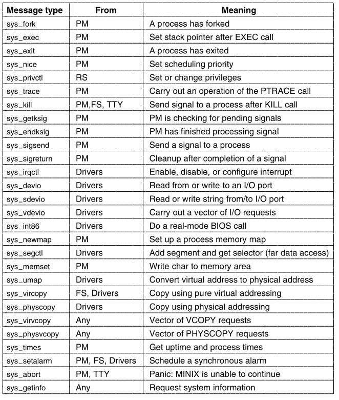
“Any” means any system process.
User processes cannot call the system task directly.
Each of these can be considered one kernel call,
although in some cases, there are multiple macros defined with different
names,
that all result in just one of the message types shown in the
figure.
In some other cases, more than one of the message types in the
figure,
are handled by a single procedure that does the work.
The main program of the system task is structured like other
tasks.
After doing necessary initialization it runs in a loop.
It gets a message, dispatches to the appropriate service
procedure,
and then sends a reply.
A few general support functions are found in the main file,
system.c,
but the main loop dispatches to a procedure in a separate file,
in the kernel/system/ directory, to process each kernel
call.
We will see how this works, and the reason for this organization,
when we discuss the implementation of the system task soon.
First, we will briefly describe the function of each kernel
call.
The message types in fall into several categories.
The first few are involved with process management:
sys_fork, sys_exec, sys_exit, and
sys_trace.
These are closely related to standard POSIX system calls.
Although nice is not a POSIX-required system call,
the command ultimately results in a sys_nice kernel
call,
to change the priority of a process.
The only one of this group that is likely to be unfamiliar is
sys_privctl.
It is used by the reincarnation server (RS),
the MINIX3 component responsible for converting processes,
started as ordinary user processes, into system processes.
sys_privctl changes the privileges of a process,
for example, to allow it to make kernel calls.
sys_privctl is used when drivers and servers,
that are not part of the boot image,
are started by the /etc/rc script.
MINIX3 drivers also can be started (or restarted) at any time;
privilege changes are needed whenever this is done.
The next group of kernel calls are related to signals.
sys_kill is related to the user-accessible (and misnamed)
system call kill.
The others in this group, sys_getksig,
sys_endksig, sys_sigsend, and
sys_sigreturn
are all used by the process manager, to get the kernel’s help in
handling signals.
The sys_irqctl, sys_devio,
sys_sdevio, and sys_vdevio
and kernel calls unique to MINIX3.
These provide the support needed for user-space device drivers.
We mentioned sys_irqctl at the start of this section.
One of its functions is to set a hardware interrupt handler,
and enable interrupts on behalf of a user-space driver.
sys_devio allows a user-space driver to query the system
task,
to read or write from an I/O port.
It involves more overhead, than would be the case,
if the driver were running in kernel space.
The next two kernel calls offer a higher level of I/O device support.
sys_sdevio can be used when a sequence of bytes or
words, i.e., a string,
is to be read from or written to a single I/O address,
as might be the case when accessing a serial port.
sys_vdevio is used to send a vector of I/O requests to
the system task.
By a vector is meant a series of (port, value) pairs.
Earlier, we described the intr_init function,
that initializes the Intel i8259 interrupt controllers.
A series of instructions writes a series of byte values.
For each of the two i8259 chips,
there is a control port that sets the mode,
and another port that receives a sequence of four bytes in the
initialization sequence.
This code executes in the kernel,
so no support from the system task is needed.
But if this were being done by a user-space process,
then a single message passing the address to a buffer,
containing 10 (port, value) pairs, would be much more efficient,
than 10 messages, each passing one port address,
and a value to be written.
The next three kernel calls shown in the above image,
involve memory in distinct ways.
The first, sys_newmap, is called by the process
manager,
when the memory used by a process changes,
so the kernel’s part of the process table can be updated.
sys_segctl and sys_memset provide a safe
interface,
to provide a process with access to memory outside its own data
space.
The memory area from 0xa0000 to 0xfffff is reserved for I/O
devices,
as we mentioned in the discussion of startup of the MINIX3 system.
Some devices use part of this memory region for I/O.
For example, video display cards expect to have data to be
displayed,
written into memory, on the card which is mapped here.
sys_segctl is used by a device driver, to obtain a
segment selector,
that will allow it to address memory in this range.
The other call, sys_memset, is used when a server wants
to write data,
into an area of memory that does not belong to it.
It is used by the process manager,
to zero out memory, when a new process is started,
to prevent the new process from reading data left by another
process.
The next group of kernel calls is for copying memory.
sys_umap converts virtual addresses to physical
addresses.
sys_vircopy and sys_physcopy copy regions
of memory,
using either virtual or physical addresses.
The next two calls, sys_virvcopy and
sys_physvcopy
are vector versions of the previous two.
As with vectored I/O requests,
these allow making a request to the system task,
for a series of memory copy operations.
sys_times obviously has to do with time,
and corresponds to the POSIX times system call.
sys_setalarm is related to the POSIX alarm system
call,
but the relation is a distant one.
The POSIX call is mostly handled by the process manager,
which maintains a queue of timers on behalf of user processes.
The process manager uses a sys_setalarm kernel call,
when it needs to have a timer set on its behalf in the kernel.
This is done only when there is a change,
at the head of the queue managed by the PM,
and does not necessarily follow every alarm call from a user
process.
The final two kernel calls are for system control.
sys_abort can originate in the process manager,
after a normal request to shutdown the system, or after a panic.
It can also originate from the tty device driver,
in response to a user pressing the Ctrl-Alt-Del key combination.
Finally, sys_getinfo is a catch-all,
that handles a diverse range of requests for information from the
kernel.
If you search through the MINIX3 C source files,
then you will find very few references to this call by its own
name.
But, if you extend your search to the header directories,
then you will find no less than 13 macros in
include/minix/syslib.h
that give another name to sys_getinfo.
An example is
sys_getkinfo(dst) sys_getinfo(GET_KINFO, dst, 0,0,0)
which is used to return the kinfo structure
(defined in include/minix/type.h)
to the process manager for use during system startup.
The same information may be needed at other times.
For example, the user command ps,
needs to know the location of the kernel’s part of the process
table,
to display information about the status of all processes!
It asks the PM,
which in turn uses the sys_getkinfo variant of
sys_getinfo
to get the information.
sys_getinfo is not the only kernel call that is invoked
by a number of different names,
defined as macros in include/minix/syslib.h.
For example, the sys_sdevio call is usually invoked by
one of the macros:
sys_insb, sys_insw, sys_outsb, or
sys_outsw.
The names were devised, to make it easy to see whether the operation is
input or output,
with data types byte or word.
Similarly, the sys_irqctl call is usually invoked by a
macro like:
sys_irqenable, sys_irqdisable, or one of
several others.
Such macros make the meaning clearer to a person reading the
code.
They also help the programmer by automatically generating constant
arguments.
++++++++++++ Cahoot-02-12
The system task is compiled from a header,
system.h,
and a C source file, system.c, in the main
kernel/ directory.
In addition, there is a specialized library of helpers,
built from source files in a subdirectory,
kernel/system/.
There is a reason for this organization.
Although MINIX3, as we describe it here,
is a general-purpose operating system,
it is also potentially useful for special purposes,
such as embedded support in a portable device.
A stripped-down version of the operating system might be adequate.
For example, a device without a disk might not need a file system.
In kernel/config.h compilation of kernel calls can be
selectively enabled and disabled.
Having the code that supports each kernel call,
linked from the library, as the last stage of compilation,
makes it easier to build a customized system.
Putting support for each kernel call in a separate file,
simplifies maintenance of the software.
But there is some redundancy between these files.
Thus we will describe only a few of the files in the
kernel/system/ directory.
We will begin by looking at the header file,
kernel/system.h.
It provides prototypes for functions,
corresponding to most of the kernel calls listed.
In addition there is a prototype for do_unused,
the function that is invoked if an unsupported kernel call is made.
Some of the message types above, correspond to macros defined
here.
These are cases where one function can handle more than one call.
The main driver for kernel calls.
Before looking at the code in system.c,
note the declaration of the call vector call_vec,
and the definition of the macro map.
call_vec is an array of pointers to functions,
which provides a mechanism for dispatching, to the function
needed,
to service a particular message by using the message type,
expressed as a number, as an index into the array.
This is a technique we will see used elsewhere in MINIX3.
The map macro is a convenient way to initialize such an array.
The macro is defined in such a way that:
trying to expand it with an invalid argument,
will result in declaring an array with a negative size,
which is impossible, and will cause a compiler error.
The top level of the system task is the procedure
sys_task.
When MINIX3 starts up,
the system task is at the head of the highest priority queue,
so the system task’s initialize function initializes the array of
interrupt hooks,
and the list of alarm timers.
The system task is used to enable interrupts,
on behalf of user-space drivers that need to respond to
interrupts,
so it makes sense to have it prepare the table.
The system task is used to set up timers,
when synchronous alarms are requested by other system processes,
so initializing the timer lists is also appropriate here.
In the call to the initialization function,
all slots in the call_vec array are filled,
with the address of the procedure do_unused,
called if an unsupported kernel call is made.
Then the rest of the function is multiple expansions of the
map macro,
each one of which, installs the address of a function,
into the proper slot in call_vec.
After a call to initialize an array of pointers to
functions,
sys_task runs in a loop.
It waits for a message,
makes a few tests to validate the message,
dispatches to the function that handles the call that corresponds to the
message type,
possibly generating a reply message,
and repeats the cycle as long as MINIX3 is running.
The tests consist of a check of the priv table entry for
the caller,
to determine that it is allowed to make this type of call,
and making sure that this type of call is valid.
The dispatch to the function that does the work is done.
The index into the call_vec array is the call number,
the function called, is the one whose address is in that cell of the
array,
the argument to the function is a pointer to the message,
and the return value is a status code.
A function may return a EDONTREPLY status,
meaning no reply message is required,
otherwise a reply message is sent.
The rest of system.c consists of functions that are
declared PUBLIC,
and that may be used by more than one of the routines that service
kernel calls,
or by other parts of the kernel.
For example, the first such function, get_priv, is used
by do_privctl,
which supports the sys_privctl kernel call.
It is also called by the kernel itself,
while constructing process table entries,
for processes in the boot image.
The name is a perhaps a bit misleading.
get_priv does not retrieve information about privileges
already assigned,
instead, it finds an available priv structure, and assigns it to the
caller.
There are two cases:
System processes each get their own entry in the priv
table.
If one is not available,
then the process cannot become a system process.
User processes all share the same entry in the table.
get_randomness is used to get seed numbers for the
random number generator,
which is a implemented as a special character device in MINIX3.
The newest Pentium-class processors include an internal cycle
counter,
and provide an assembly language instruction that can read it.
This is used if available, otherwise a function is called,
which reads a register in the clock chip.
send_sig generates a notification to a system
process,
after setting a bit in the s_sig_pending bitmap,
of the process to be signaled.
The bit is set.
Because the s_sig_pending bitmap is part of a priv
structure,
this mechanism can only be used to notify system processes.
All user processes share a common priv table entry,
and therefore fields like the s_sig_pending bitmap cannot
be shared,
and are not used by user processes.
Verification that the target is a system process is made,
before send_sig is called.
The call comes either as:
a result of a sys_kill kernel call,
or from the kernel, when kprintf is sending a string of
characters.
In the former case, the caller determines whether the target is a system
process.
In the latter case, the kernel only prints to the configured output
process,
which is either the console driver or the log driver,
both of which are system processes.
The next function, cause_sig, is called to send a signal
to a user process.
It is used when a sys_kill kernel call targets a user
process.
It is here in system.c because it also may be called
directly by the kernel in response to an exception triggered by the user
process.
As with send_sig a bit must be set in the recipient’s
bitmap for pending signals,
but for user processes this is not in the priv table,
it is in the process table.
The target process must also be made not ready by a call to
lock_dequeue,
and its flags (also in the process table) updated to indicate it is
going to be signaled.
Then a message is sent—but not to the target process.
The message is sent to the process manager,
which takes care of all of the aspects of signaling a process that can
be dealt with by a user-space system process.
Next come three functions which all support the sys_umap
kernel call.
Processes normally deal with virtual addresses,
relative to the base of a particular segment.
Sometimes they need to know the absolute (physical) address of a region
of memory,
for example, if a request is made for copying between memory
regions,
belonging to two different segments.
There are three ways a virtual memory address might be specified:
The normal one for a process,
is relative to one of the memory segments, text, data, or stack,
assigned to a process, and recorded in its process table slot.
Requesting conversion of virtual to physical memory, in this case, is
done by a call to umap_local.
The second kind of memory reference,
is to a region of memory that is outside the text, data, or stack areas
allocated to a process,
but for which the process has some responsibility.
Examples of this are a video driver or an Ethernet driver,
where the video or Ethernet card might have a region of memory,
mapped in the region from 0xa0000 to 0xfffff,
which is reserved for I/O devices.
Another example is the memory driver,
which manages the ramdisk, and also can provide access to any part of
the memory,
through the devices /dev/mem and
/dev/kmem.
Requests for conversion of such memory references,
from virtual to physical, are handled by
umap_remote.
Finally, a memory reference may be to memory that is used by the
BIOS.
This is considered to include both the lowest 2 KB of memory,
below where MINIX3 is loaded, and the region from 0x90000 to
0xfffff,
which includes some RAM above where MINIX3 is loaded,
plus the region reserved for I/O devices.
This could also be handled by umap_remote,
but using the third function, umap_bios,
ensures that a check will be made,
that the memory being referenced is really in this region.
The last function defined in system.c is
virtual_copy.
Most of this function is a C switch,
which uses one of the three umap_* functions just
described,
to convert virtual addresses to physical addresses.
This is done for both the source and destination addresses.
The actual copying is done by a call to the assembly language routine
phys_copy in klib386.s.
Each of the functions, with a name of the form
do_xyz,
has its source code in a file in a subdirectory:
kernel/system/do_xyz.c.
In the kernel/ directory the Makefile contains
a line:
cd system && $(MAKE) –$(MAKEFLAGS) $@
which compiles the files in kernel/system/ into a
library, system.a
in the main kernel/ directory.
When control returns to the main kernel directory,
another line in the Makefile causes this local library to
be searched first,
when the kernel object files are linked.
We focus on two files the kernel/system/ directory
now.
These were chosen,
because they represent two general classes of support,
that the system task provides.
One category of support is:
access to kernel data structures,
on behalf of any user-space system process,
that needs such support.
We will describe system/do_setalarm.c as an example of this
category.
The other general category is:
support for specific system calls,
that are mostly managed by userspace processes,
but which need to carry out some actions in kernel space.
We have chosen system/do_exec.c as our example.
The sys_setalarm kernel call is somewhat similar to
sys_irqenable,
which we mentioned in the discussion of interrupt handling in the
kernel.
sys_irqenable sets up an address to an interrupt
handler,
to be called when an IRQ is activated.
The handler is a function within the system task,
generic_handler.
It generates a notify message to the device driver process,
that should respond to the interrupt.
system/do_setalarm.c contains code to manage
timers,
in a way similar to how interrupts are managed.
A sys_setalarm kernel call initializes a timer for a
user-space system process,
that needs to receive a synchronous alarm,
and it provides a function to be called,
to notify the user-space process when the timer expires.
It can also ask for cancellation of a previously scheduled alarm,
by passing zero in the expiration time field of its request
message.
The operation is simple;
information from the message is extracted.
The most important items are the time when the timer should go
off,
and the process that needs to know about it.
Every system process has its own timer structure in the
priv table.
In the code, the timer structure is located,
and the process number and the address of a function,
cause_alarm,
to be executed when the timer expires, are entered.
If the timer was already active,
then sys_setalarm returns the time remaining in its reply
message.
A return value of zero means the timer is not active.
There are several possibilities to be considered:
The timer might previously have been deactivated;
a timer is marked inactive by storing a special value,
TMR_NEVER in its exp_time field .
As far as the C code is concerned, this is just a large integer,
so an explicit test for this value is made,
as part of checking whether the expiration time has passed.
The timer might indicate a time that has already passed.
This is unlikley to happen, but it is easy to check.
The timer might also indicate a time in the future.
In either of the first two cases the reply value is zero,
otherwise the time remaining is returned.
Finally, the timer is reset or set.
At this level, this is done by setting the desired expiration
time,
into the correct field of the timer structure,
and calling another function to do the work.
Resetting the timer does not require storing a value.
We will see the functions reset and set
soon,
their code is in the source file for the clock task.
But since the system task and the clock task are both compiled into the
kernel image,
all functions declared PUBLIC are accessible.
There is one other function defined in
do_setalarm.c.
This is cause_alarm, the watchdog function,
whose address is stored in each timer,
so it can be called when the timer expires.
It is simple.
It generates a notify message,
to the process whose process number is also stored in the timer
structure.
Thus the synchronous alarm within the kernel is converted,
into a message to the system process that asked for an alarm.
When we talked about the initialization of timers a few pages
back
(and in this section as well)
we referred to synchronous alarms requested by system processes.
That will not make complete sense at this point,
These questions will be dealt with in the next section,
when we discuss the clock task.
There are so many interconnected parts in an operating system,
that it is almost impossible to order all topics,
in a way that does not occasionally require a forward reference,
to a part that has not been already been explained.
This is particularly true when discussing implementation.
If we were not dealing with a real operating system,
then we could potentially avoid bringing up messy details like this.
In a totally theoretical discussion of operating system
principles,
we would probably never mention a system task.
In a theoretical OS book, we could just wave our arms,
and ignore the real problems,
like giving operating system components in user space limited and
controlled access,
to privileged resources like interrupts and I/O ports.
Another file in the kernel/system/ directory is
do_exec.c.
Most of the work of the exec system call is done within
the process manager.
The process manager sets up a stack for a new program,
that contains the arguments and the environment.
Then it passes the resulting stack pointer to the kernel using
sys_exec,
which is handled by do_exec.
The stack pointer is set in the kernel part of the process table,
and if the process being executed with exec is using an
extra segment,
then the assembly language phys_memset function, defined in
klib386.s is called,
to erase any data that might be left over,
from previous use of that memory region.
An exec call causes a slight anomaly.
The process invoking the call sends a message to the process manager,
and blocks.
With other system calls, the resulting reply would unblock it.
With exec there is no reply,
because the newly loaded core image is not expecting a reply.
Therefore, do_exec unblocks the process itself.
The next line makes the new image ready to run,
using the lock_enqueue function,
that protects against a possible race condition.
Finally, the command string is saved,
so the process can be identified, when the user invokes the
ps command,
or presses a function key to display data from the process table.
To finish our discussion of the system task,
we will look at its role in handling a typical operating service,
providing data in response to a read system call.
When a user does a read call,
the file system checks its cache,
to see if it has the block needed.
If not, it sends a message to the appropriate disk driver,
to load it into the cache.
Then, the file system sends a message to the system task,
telling it to copy the block to the user process.
In the worst case, eleven messages are needed to read a block;
in the best case, four messages are needed.
Both cases are shown:
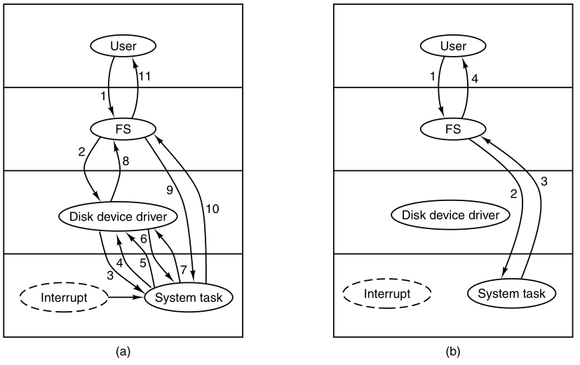
(a) Worst case for reading a block requires eleven messages.
(b) Best case for reading a block requires four messages.
In (a), message 3 asks the system task to execute I/O
instructions;
4 is the ACK.
When a hardware interrupt occurs,
the system task tells the waiting driver about this event with message
5.
Messages 6 and 7 are a request to copy the data to the FS cache and the
reply,
message 8 tells the FS the data is ready,
and messages 9 and 10 are a request to copy the data from the cache to
the user, and the reply.
Finally message 11 is the reply to the user.
In (b), the data is already in the cache,
messages 2 and 3 are the request to copy it to the user and the
reply.
These messages are a source of overhead in MINIX3,
and are the price paid for the highly modular design.
More modern microkernels improve efficiency to monolithic kernel
levels.
Kernel calls to request copying of data,
are probably the most heavily used ones in MINIX3.
We have already seen the part of the system task,
that ultimately does the work,
in system.c, the function virtual_copy.
One way to deal with some of the inefficiency of the message passing
mechanism,
is to pack multiple requests into a message.
The sys_virvcopy and sys_physvcopy kernel
calls do this.
The content of a message that invokes one of these calls,
is a pointer to a vector specifying multiple blocks,
to be copied between memory locations.
Both are supported by do_vcopy, which executes a
loop,
extracting source and destination addresses, and block lengths,
and calling phys_copy repeatedly, until all the copies are
complete.
We will see in the next section that disk devices have a similar
ability,
to handle multiple transfers based on a single request.
Recall the structure of Minix3:
Clocks (also called timers) are essential for any timesharing
system.
They maintain the time of day,
and prevent one process from monopolizing the CPU.
The MINIX3 clock task has some resemblance to a device driver,
in that it is driven by interrupts, generated by a hardware
device.
However, the clock is neither a block device, like a disk,
nor a character device, like a terminal.
An interface to the clock is not provided by a file in the
/dev/ directory.
The clock task executes in kernel space,
and cannot be accessed directly by user-space processes.
It has access to all kernel functions and data.
User-space processes can only access it via the system task.
In this section we will first look at clock hardware and software in
general,
and then we will see how these ideas are applied in MINIX3.
Two types of clocks are used in computers,
and both are quite different from the clocks and watches used by
people.
The simpler clocks are tied to the 110- or 220-volt power line,
and cause an interrupt on every voltage cycle, at 50 or 60 Hz.
These are essentially extinct in modern PCs.
A programmable clock is built out of three components:
a crystal oscillator, a counter, and a holding register, as shown:
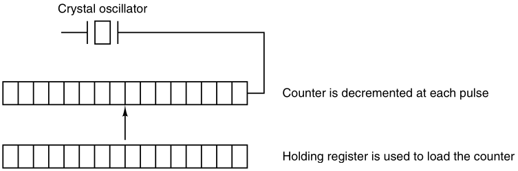
When a piece of quartz crystal is properly cut and mounted under
tension,
it can be made to generate a periodic signal of very high
accuracy,
typically in the range of 5 to 200 MHz, depending on the crystal
chosen.
At least one such circuit is usually found in any computer,
providing a synchronizing signal to the computer’s various
circuits.
This signal is fed into the counter, to make it count down to
zero.
When the counter gets to zero, it causes a CPU interrupt.
Computers whose advertised clock rate is higher than 200 MHz,
normally use a slower clock, and a clock multiplier circuit.
Programmable clocks typically have several modes of operation:
In one-shot mode, when the clock is started,
it copies the value of the holding register into the counter,
and then decrements the counter at each pulse from the crystal.
When the counter gets to zero,
it causes an interrupt and stops,
until it is explicitly started again, by the software.
In square-wave mode, after getting to zero and causing the
interrupt,
the holding register is automatically copied into the counter,
and the whole process is repeated again indefinitely.
These periodic interrupts are called clock ticks.
Programmable clock’s interrupt frequency can be controlled by
software.
If a 1-MHz crystal is used,
then the counter is pulsed every microsecond.
With 16-bit registers, interrupts can be programmed,
to occur at intervals from 1 microsecond to 65.536 milliseconds.
Programmable clock chips usually contain two or three independently
programmable clocks,
and have many other options as well
(e.g., counting up instead of down, interrupts disabled, and more).
To prevent the current time from being lost when the computer’s power
is turned off,
most computers have a battery-powered backup clock,
implemented with the kind of low-power circuitry used in digital
watches.
The battery clock can be read at startup.
If the backup clock is not present,
the software may ask the user for the current date and time.
There is also a standard protocol for a networked system,
to get the current time from a remote host.
The time is then translated into the number of seconds since a fixed
time,
12am Universal Coordinated Time (UTC) on Jan. 1, 1970
(formerly known as Greenwich Mean Time),
as UNIX and MINIX3 do,
or since some other benchmark.
Clock ticks are counted by the running system,
and every time a full second has passed,
the real time is incremented by one count.
MINIX3 (and most UNIX systems) do not take into account leap
seconds,
of which there have been 23 since 1970.
This is not considered a serious flaw.
Usually, utility programs are provided,
to manually set the system clock and the backup clock,
and to synchronize the two clocks.
All but the earliest IBM-compatible computers have a separate clock
circuit,
that provides timing signals for the CPU, internal data buses, and other
components.
This is the clock that is meant when people speak of CPU clock
speeds,
measured in Megahertz on the earliest personal computers,
and in Gigahertz on modern systems.
The basic circuitry of quartz crystals, oscillators, and counters is the
same,
but the requirements are much different,
such that modern computers have independent clocks for CPU control and
timekeeping.
All the clock hardware does is generate interrupts at known
intervals.
Everything else involving time must be done by the software, the clock
driver.
The exact duties of the clock driver vary among operating systems,
but usually include most of the following:
The first clock function, maintaining the time of day, is not
difficult.
It just requires incrementing a counter at each clock tick, as mentioned
before.
The only thing to watch out for is the number of bits in the time-of-day
counter.
With a clock rate of 60 Hz, a 32-bit counter will overflow in just over
2 years.
Clearly the system cannot store the real time as the number of ticks
since Jan. 1, 1970 in 32 bits.
Three approaches can be taken to solve this problem:
The first way is to use a 64-bit counter,
although doing so makes maintaining the counter more expensive,
since it has to be done many times a second.
The second way is to maintain the time of day in seconds,
rather than in ticks, using a subsidiary counter to count ticks until a
whole second has been accumulated.
This method will work until well into the twenty-second century.
The third approach is to count ticks,
but to do that relative to the time the system was booted,
rather than relative to a fixed external moment.
When the backup clock is read,
or the user types in the real time,
the system boot time is calculated,
from the current time-of-day value,
and stored in memory in any convenient form.
When the time of day is requested,
the stored time of day is added to the counter,
to get the current time of day.
All three approaches are shown:
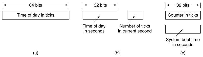
Three ways to maintain the time of day.
The second clock function is preventing processes from running too
long.
Whenever a process is started,
the scheduler should initialize a counter,
to the value of that process’ quantum in clock ticks.
At every clock interrupt,
the clock driver decrements the quantum counter by 1.
When it gets to zero,
the clock driver calls the scheduler,
to set up another process.
The third clock function is doing CPU accounting.
The most accurate way to do it is to start a second timer,
distinct from the main system timer,
whenever a process is started.
When that process is stopped,
the timer can be read out,
to tell how long the process has run.
The second timer should be saved when an interrupt occurs,
and restored afterward.
A less accurate, but much simpler, way to do accounting,
is to maintain in a global variable,
a pointer to a process table entry,
for the currently running process.
At every clock tick, a field in the current process’ entry is
incremented.
In this way, every clock tick is “charged” to the process running at the
time of the tick.
A minor problem with this strategy is that:
if many interrupts occur during a process’ run,
then it is still charged for a full tick,
even though it did not get much work done.
Properly accounting for the CPU during interrupts is too
expensive,
and is rarely done.
In MINIX3 and many other systems,
a process can request that the operating system give it a warning after
a certain interval.
The warning is usually a signal, interrupt, message, or something
similar.
One application requiring such warnings is networking,
in which a packet not acknowledged within a certain time interval,
must be retransmitted.
If the clock driver had enough clocks,
then it could set a separate clock for each request.
This not being the case,
it must simulate multiple virtual clocks,
with a single physical clock.
One way is to maintain a table,
in which the signal time for all pending timers is kept,
as well as a variable giving the time of the next closest one in
time.
Whenever the time of day is updated,
the driver checks to see if the closest signal has occurred.
If it has, then the table is searched for the next one to occur.
If many signals are expected,
then it is more efficient to simulate multiple clocks,
by chaining all the pending clock requests together,
sorted on time, in a linked list, as shown:
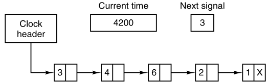
Simulating multiple timers with a single clock.
Each entry on the list tells how many clock ticks following the previous
one,
to wait before causing a signal.
In this example, signals are pending for 4203, 4207, 4213, 4215, and
4216.
In the image, a timer has just expired.
The next interrupt occurs in 3 ticks,
and 3 has just been loaded.
On each tick, Next signal is decremented.
When it gets to 0,
the signal corresponding to the first item on the list is caused,
and that item is removed from the list.
Then Next signal is set to the value in the entry now at the head of the
list,
in this example, 4.
Using absolute times, rather than relative times,
is more convenient in many cases,
and that is the approach used by MINIX3.
During a clock interrupt, the clock driver has several things to
do.
These things include:
incrementing the real time,
decrementing the quantum and checking for 0,
doing CPU accounting,
and decrementing the alarm counter.
However, each of these operations has been carefully arranged,
to be very fast, because they have to be repeated many times a
second.
Parts of the operating system also need to set timers.
These are called watchdog timers.
When we study the hard disk driver,
we will see that
each time the disk controller is sent a command,
a wakeup call is scheduled,
so an attempt at recovery can be made,
if the command fails completely.
Floppy disk drivers use timers,
to wait for the disk motor to get up to speed,
and if no activity occurs for a while,
to shut down the motor.
Some printers with a movable print head can print at 120
characters/sec (8.3 msec/character)
but cannot return the print head to the left margin in 8.3 msec,
so after typing a carriage return, the terminal driver must delay.
The mechanism used by the clock driver to handle watchdog
timers,
is the same as for user signals.
The only difference is that when a timer goes off,
instead of causing a signal,
the clock driver calls a procedure supplied by the caller.
The procedure is part of the caller’s code.
This presented a problem in the design of MINIX3,
since one of the goals was to remove drivers from the kernel’s address
space.
The system task, which is in kernel space,
can set alarms on behalf of some user-space processes,
and then notify them when a timer goes off.
We will elaborate on this mechanism further on.
The last thing in our list is profiling.
Some operating systems provide a profiling mechanism,
with which a user program can have the system build up a histogram of
its program counter,
so it can see where it is spending its time.
When profiling is a possibility,
at every tick the driver checks to see if the current process is being
profiled,
and if so, computes the bin number (a range of addresses),
corresponding to the current program counter.
It then increments that bin by one.
This mechanism can also be used to profile the system itself.
+++++++++++++ Cahoot-02-13
The MINIX3 clock driver is contained in the file
kernel/clock.c.
It can be considered to have three functional parts.
First, like the device drivers that we will see in the next
chapter,
there is a task mechanism which runs in a loop,
waiting for messages and dispatching to subroutines,
that perform the action requested in each message.
However, this structure is almost vestigial in the clock task.
The message mechanism is expensive,
requiring all the overhead of a context switch.
So for the clock, this is used only when there is a substantial amount
of work to be done.
Only one kind of message is received,
there is only one subroutine to service the message,
and a reply message is not sent when the job is done.
The second major part of the clock software is the interrupt
handler,
that is activated 60 times each second.
It does basic timekeeping,
updating a variable that counts clock ticks since the system was
booted.
It compares this with the time for the next timer expiration.
It also updates counters,
that track how much of the quantum of the current process has been
used,
and how much total time the current process has used.
If the interrupt handler detects that:
a process has used its quantum,
or that a timer has expired,
then it generates the message that goes to the main task loop.
Otherwise no message is sent.
The strategy here is that for each clock tick,
the handler does as little as necessary,
as fast as possible.
The costly main task is activated only when there is substantial work to
do.
The third general part of the clock software is a collection of
subroutines,
that provide general support,
but which are not called in response to clock interrupts,
either by the interrupt handler or by the main task loop.
One of these subroutines is coded as PRIVATE,
and is called before the main task loop is entered.
It initializes the clock,
which entails writing data to the clock chip,
to cause it to generate interrupts at the desired intervals.
The initialization routine also puts the address of the interrupt
handler in the right place,
to be found when the clock chip triggers the IRQ 8 input to the
interrupt controller chip,
and then enables that input to respond.
The rest of the subroutines in clock.c are declared
PUBLIC,
and can be called from anywhere in the kernel binary.
In fact none of them are called from clock.c itself.
They are mostly called by the system task in order to service system
calls related to time.
These subroutines do such things as reading the time-since-boot
counter,
for timing with clock-tick resolution,
or reading a register in the clock chip itself,
for timing that requires microsecond resolution.
Other subroutines are used to set and reset timers.
Finally, a subroutine is provided to be called when MINIX3 shuts
down.
This one resets the hardware timer parameters to those expected by the
BIOS.
The main loop of the clock task accepts only a single kind of
message,
HARD_INT, which comes from the interrupt handler.
Anything else is an error.
Furthermore, it does not receive this message for every clock tick
interrupt,
although the subroutine called each time a message is received is named
do_clocktick.
A message is received, and do_clocktick is called only if
process scheduling is needed or a timer has expired.
The interrupt handler runs every time the counter in the clock chip
reaches zero and generates an interrupt.
This is where the basic timekeeping work is done.
In MINIX3 the time is kept using the third timekeeping method, (c) in
previous image.
However, in clock.c only the counter for ticks since boot
is maintained;
records of the boot time are kept elsewhere.
The clock software supplies only the current tick count to aid a system
call for the real time.
Further processing is done by one of the servers.
This is consistent with the MINIX3 strategy of moving functionality to
processes that run in user space.
In the interrupt handler the local counter is updated for each
interrupt received.
When interrupts are disabled ticks are lost.
In some cases it is possible to correct for this effect.
A global variable is available for counting lost ticks,
and it is added to the main counter and then reset to zero each time the
handler is activated.
In the implementation section we will see an example of how this is
used.
The handler also affects variables in the process table,
for billing and process control purposes.
A message is sent to the clock task only if the current time has passed
the expiration time of the next scheduled timer or if the quantum of the
running process has been decremented to zero.
Everything done in the interrupt service is a simple integer
operation,
arithmetic, comparison, logical AND/OR, or assignment,
which a C compiler can translate easily into basic machine
operations.
At worst there are five additions or subtractions and six
comparisons,
plus a few logical operations and assignments in completing the
interrupt service.
In particular there is no subroutine call overhead.
A few pages back we left hanging the question of how user-space
processes can be provided with watchdog timers,
which ordinarily are thought of as users-upplied procedures that are
part of the user’s code and are executed when a timer expires.
Clearly, this can not be done in MINIX3.
But we can use a synchronous alarm to bridge the gap from the kernel to
user space.
This is a good time to explain what is meant by a synchronous
alarm.
A signal may arrive or a conventional watchdog may be activated without
any relation to what part of a process is currently executing,
so these mechanisms are asynchronous.
A synchronous alarm is delivered as a message,
and thus can be received only when the recipient has executed
receive.
So we say it is synchronous because it will be received only when the
receiver expects it.
If the notify method is used to inform a recipient of an alarm,
the sender does not have to block,
and the recipient does not have to be concerned with missing the
alarm.
Messages from notify are saved if the recipient is not waiting.
A bitmap is used, with each bit representing a possible source of a
notification.
Watchdog timers take advantage of the timer_t type
s_alarm_timer field that exists in each element of the priv
table.
Each system process has a slot in the priv table.
To set a timer, a system process in user space makes a
sys_setalarm call,
which is handled by the system task.
The system task is compiled in kernel space,
and thus can initialize a timer on behalf of the calling process.
Initialization entails putting the address of a procedure to execute
when the timer expires into the correct field,
and then inserting the timer into a list of timers.
The procedure to execute has to be in kernel space too, of
course.
The system task contains a watchdog function,
cause_alarm,
which generates a notify when it goes off,
causing a synchronous alarm for the user.
This alarm can invoke the user-space watchdog function.
Within the kernel binary this is a true watchdog,
but for the process that requested the timer,
it is a synchronous alarm.
It is not the same as having the timer execute a procedure in the
target’s address space.
There is a bit more overhead,
but it is simpler than an interrupt.
What we wrote above was qualified: we said that the system task can
set alarms on behalf of some user-space processes.
The mechanism just described works only for system processes.
Each system process has a copy of the priv structure,
but a single copy is shared by all non-system (user) processes.
The parts of the priv table that cannot be shared,
such as the bitmap of pending notifications and the timer,
are not usable by user processes.
The solution is this: the process manager manages timers on behalf of
user processes in a way similar to the way the system task manages
timers for system processes.
Every process has a timer_t field of its own in the process
manager’s part of the process table.
When a user process makes an alarm system call to ask for an alarm to
be set,
it is handled by the process manager,
which sets up the timer and inserts it into its list of timers.
The process manager asks the system task to send it a notification when
the first timer in the PM’s list of timers is scheduled to expire.
The process manager only has to ask for help when the head of its chain
of timers changes,
either because the first timer has expired or has been cancelled,
or because a new request has been received that must go on the chain
before the current head.
This is used to support the POSIX-standard alarm system call.
The procedure to execute is within the address space of the process
manager.
When executed, the user process that requested the alarm is sent a
signal,
rather than a notification.
A procedure is provided in clock.c that provides
microsecond resolution timing.
Delays as short as a few microseconds may be needed by various I/O
devices.
There is no practical way to do this using alarms and the message
passing interface.
The counter that is used for generating the clock interrupts can be read
directly.
It is decremented approximately every 0.8 microseconds,
and reaches zero 60 times a second, or every 16.67 milliseconds.
To be useful for I/O timing it would have to be polled by a procedure
running in kernel-space,
but much work has gone into moving drivers out of kernel-space.
Currently this function is used only as a source of randomness for the
random number generator.
More use might be made of it on a very fast system,
but this is a future project.
The image below summarizes the various services provided directly or
indirectly by clock.c.
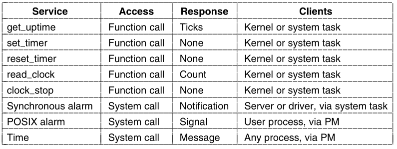
The time-related services supported by the clock driver.
There are several functions declared PUBLIC that can be called from
the kernel or the system task.
All other services are available only indirectly,
by system calls ultimately handled by the system task.
Other system processes can ask the system task directly,
but user processes must ask the process manager,
which also relies on the system task.
The kernel or the system task can get the current uptime,
or set or reset a timer without the overhead of a message.
The kernel or the system task can also call
read_clock,
which reads the counter in the timer chip,
to get time in units of approximately 0.8 microseconds.
The clock_stop function is intended to be called only when
MINIX3 shuts down.
It restores the BIOS clock rate.
A system process, either a driver or a server,
can request a synchronous alarm,
which causes activation of a watchdog function in kernel space and a
notification to the requesting process.
A POSIX-alarm is requested by a user process by asking the process
manager,
which then asks the system task to activate a watchdog.
When the timer expires,
the system task notifies the process manager,
and the process manager delivers a signal to the user process.
The clock task uses no major data structures,
but several variables are used to keep track of time.
The variable realtime is basic;
it counts all clock ticks.
A global variable, lost_ticks, is defined in
glo.h.
This variable is provided for the use of any function that executes in
kernel space that might disable interrupts long enough that one or more
clock ticks could be lost.
It currently is used by the int86 function in
klib386.s.
Int86 uses the boot monitor to manage the transfer of control to the
BIOS,
and the monitor returns the number of clock ticks counted while the BIOS
call was busy in the ecx register just before the return to the
kernel.
This works because, although the clock chip is not triggering the MINIX3
clock interrupt handler when the BIOS request is handled,
the boot monitor can keep track of the time with the help of the
BIOS.
The clock driver accesses several other global variables.
It uses proc_ptr, prev_ptr, and
bill_ptr to reference the process table entry for:
the currently running process,
the process that ran previously,
and the process that gets charged for time.
Within these process table entries it accesses various fields,
including p_user_time and p_sys_time for
accounting,
and p_ticks_left for counting down the quantum of a
process.
When MINIX3 starts up, all the drivers are called.
Most of them do some initialization then try to get a message and
block.
The clock driver, clock_task, does that too.
First it calls init_clock to initialize the programmable
clock frequency to 60 Hz.
When a message is received, it calls do_clocktick if the
message was a HARD_INT.
Any other kind of message is unexpected and treated as an error.
do_clocktick is not called on each tick of the
clock,
so its name is not an exact description of its function.
It is called when the interrupt handler has determined there might be
something important to do.
One of the conditions that results in running do_clocktick
is the current process using up all of its quantum.
If the process is preemptable (the system and clock tasks are not) a
call to lock_dequeue followed immediately by a call to
lock_enqueue removes the process from its queue,
then makes it ready again and reschedules it.
The other thing that activates do_clocktick is expiration
of a watchdog timer.
Timers and linked lists of timers are used so much in MINIX3 that a
library of functions to support them was created.
The library function tmrs_exptimers runs the watchdog
functions for all expired timers and deactivates them.
init_clock is called only once, when the clock task is
started.
There are several places one could point to and say,
“This is where MINIX3 starts running.” This is a candidate;
the clock is essential to a preemptive multitasking system.
init_clock writes three bytes to the clock chip that set
its mode and set the proper count into the master register.
Then it registers its process number, IRQ,
and handler address so interrupts will be directed properly.
Finally, it enables the interrupt controller chip to accept clock
interrupts.
The next function, clock_stop, undoes the initialization
of the clock chip.
It is declared PUBLIC and is not called from anywhere in
clock.c.
It is placed here because of the obvious similarity to
init_clock.
It is only called by the system task when MINIX3 is shut down and
control is to be returned to the boot monitor.
As soon as (or, more accurately, 16.67 milliseconds after)
init_clock runs,
the first clock interrupt occurs,
and clock interrupts repeat 60 times a second as long as MINIX3
runs.
The code in clock_handler probably runs more frequently
than any other part of the MINIX3 system.
Consequently, clock_handler was built for speed.
The only subroutine calls are only needed if running on an obsolete IBM
PS/2 system.
The update of the current time (in ticks) is done.
Then user and accounting times are updated.
Decisions were made in the design of the handler that might be
questioned.
Two tests are done, and if either condition is true the clock task is
notified.
The do_clocktick function called by the clock task repeats
both tests to decide what needs to be done.
This is necessary because the notify call used by the handler cannot
pass any information to distinguish different conditions.
We leave it to the reader to consider alternatives and how they might be
evaluated.
The rest of clock.c contains utility functions we have
already mentioned.
get_uptime just returns the value of
realtime,
which is visible only to functions in clock.c.
set_timer and reset_timer use other functions
from the timer library that take care of all the details of manipulating
a chain of timers.
Finally, read_clock reads and returns the current count in
the clock chip’s countdown register.
To hide the effects of interrupts,
operating systems provide a conceptual model consisting of sequential
processes running in parallel.
Processes can communicate with each other using interprocess
communication primitives,
such as semaphores, monitors, or messages.
These primitives are used to ensure that no two processes are ever in
their critical sections at the same time.
A process can be running, runnable, or blocked,
and can change state when it or another process executes one of the
interprocess communication primitives.
Interprocess communication primitives can be used to solve such
problems as:
the producer-consumer, dining philosophers, and reader-writer.
Even with these primitives, care has to be taken to avoid errors and
deadlocks.
Many scheduling algorithms are known, including:
round-robin, priority scheduling, multilevel queues, and policy-driven
schedulers.
MINIX3 supports the process concept and provides messages for
interprocess communication.
Messages are not buffered, so a send succeeds only when the receiver is
waiting for it.
Similarly, a receive succeeds only when a message is already
available.
If either operation does not succeed, the caller is blocked.
MINIX3 also provides a non-blocking supplement to messages with a notify
primitive.
An attempt to send a notify to a receiver that is not waiting results in
a bit being set,
which triggers notification when a receive is done later.
As an example of the message flow,
consider a user doing a read.
The user process sends a message to the FS requesting it.
If the data are not in the FS’ cache,
the FS asks the driver to read it from the disk.
Then the FS blocks waiting for the data.
When the disk interrupt happens, the system task is notified,
allowing it to reply to the disk driver, which then replies to the
FS.
At this point, the FS asks the system task to copy the data from its
cache,
where the newly requested block has been placed, to the user.
Remember the worst and best case for reading messages above.
Process switching may follow an interrupt.
When a process is interrupted, a stack is created within the process
table entry of the process,
and all the information needed to restart it is put on the new
stack.
Any process can be restarted by setting the stack pointer to point to
its process table entry and initiating a sequence of instructions to
restore the CPU registers,
culminating with an iretd instruction.
The scheduler decides which process table entry to put into the stack
pointer.
Interrupts cannot occur when the kernel itself is running.
If an exception occurs when the kernel is running,
then the kernel stack, rather than a stack within the process table, is
used.
When an interrupt has been serviced, a process is restarted.
The MINIX3 scheduling algorithm uses multiple priority queues.
System processes normally run in the highest priority queues and user
processes in lower priority queues,
but priorities are assigned on a process-by-process basis.
A process stuck in a loop may have its priority temporarily
reduced;
the priority can be restored when other processes have had a chance to
run.
The nice command can be used to change the priority of a
process within defined limits.
Processes are run round robin for a quantum that can vary per
process.
However, after a process has blocked and becomes ready again it will be
put on the head of its queue with just the unused part of its
quantum.
This is intended to give faster response to processes doing I/O.
Device drivers and servers are allowed a large quantum,
as they are expected to run until they block.
However, even system processes can be preempted if they run too
long.
The kernel image includes a system task which facilitates
communication of user-space processes with the kernel.
It supports the servers and device drivers by performing privileged
operations on their behalf.
In MINIX3, the clock task is also compiled with the kernel.
It is not a device driver in the ordinary sense.
User-space processes cannot access the clock as a device.`