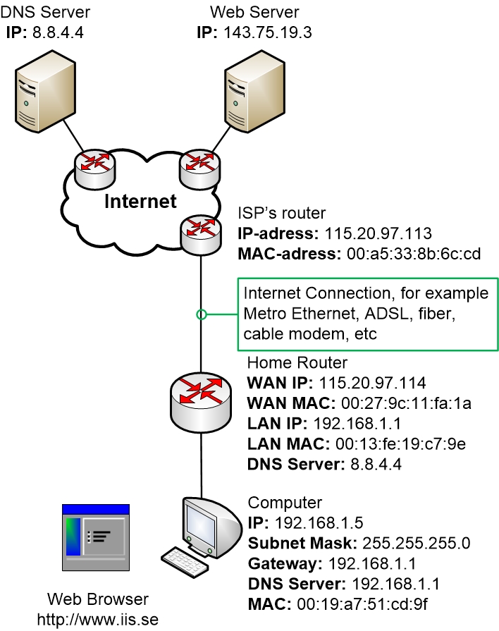
Now let’s start with the traffic example walk-through!
Previous: 08-Wireless.html
This part is divided into numerous sub-steps
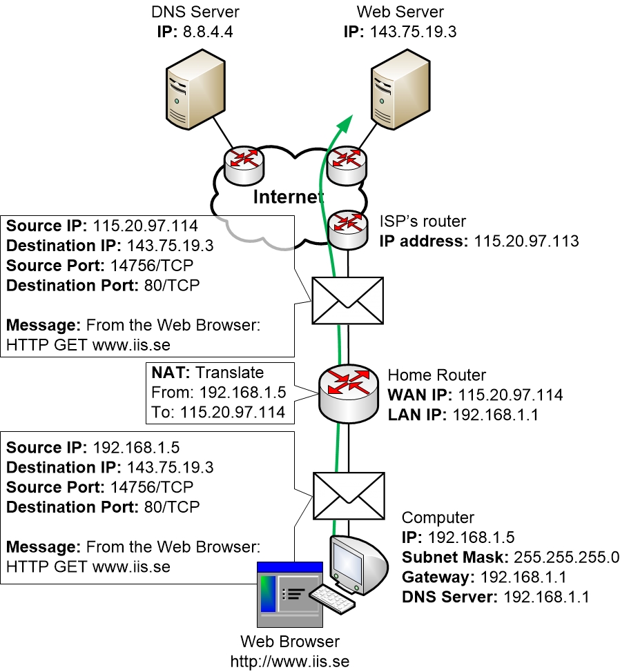
Here you can see the returning TCP SYN-ACK response from the Web
Server to the computer:
“Okay, I’m good to set up a session and I confirm that I got your
message”
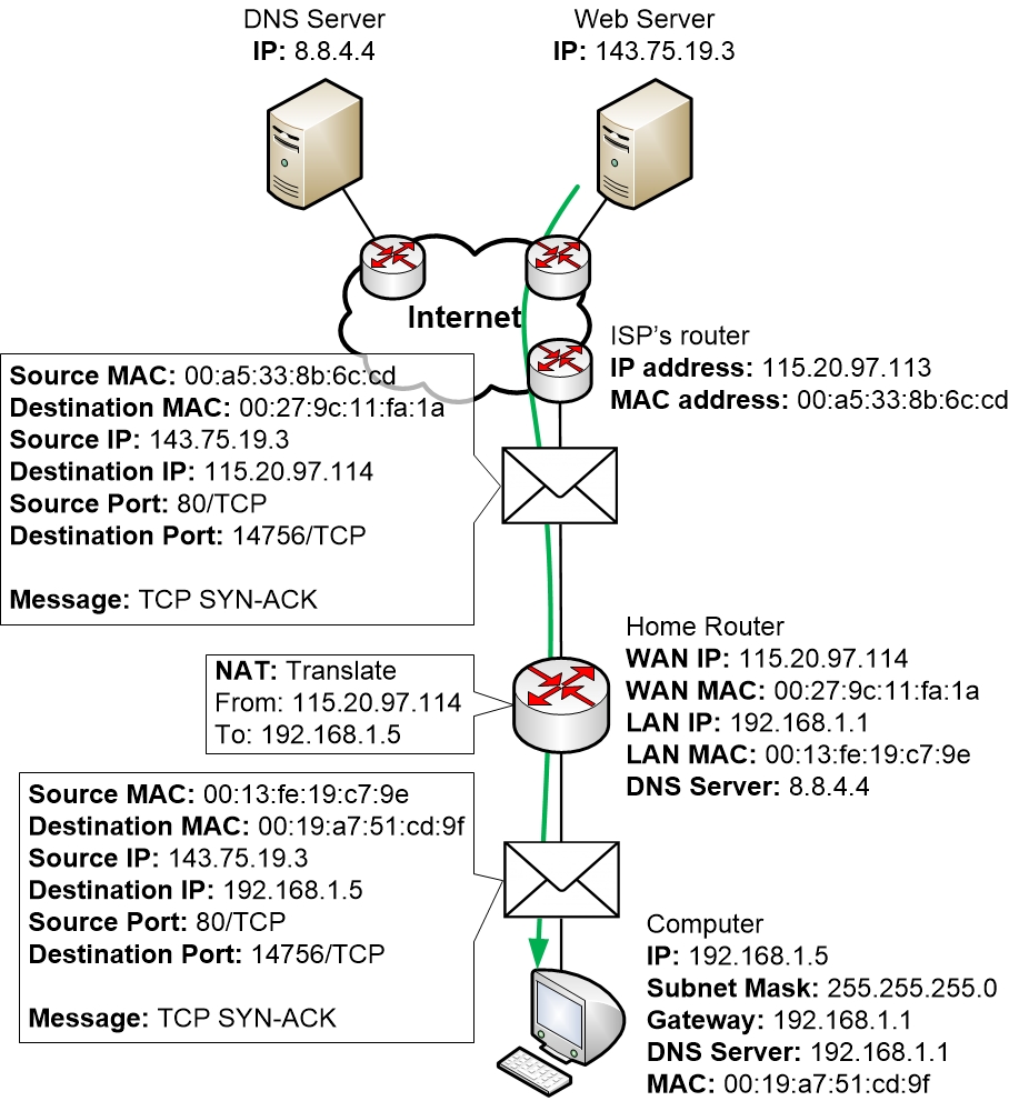
The packet matches the NAT table entry on the router, so that the router
can see which LAN computer it should forward the packet to and how it
should perform NAT on the packet.
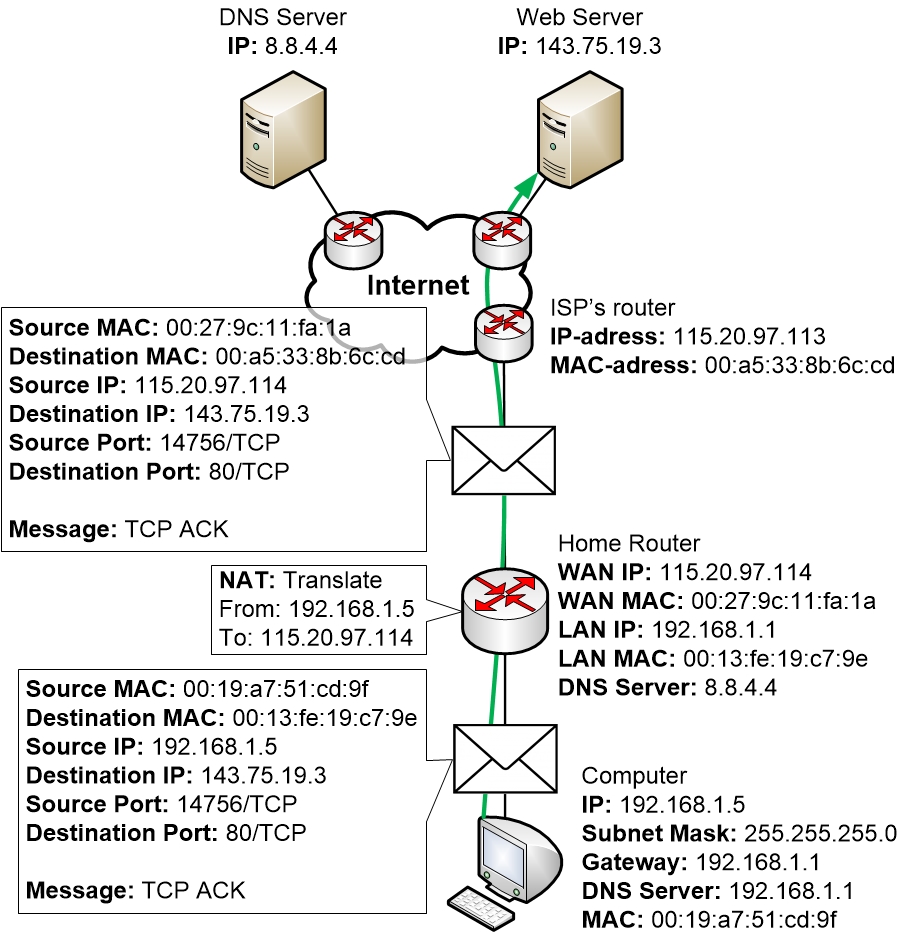
Finally, a TCP ACK is sent from the computer to the Web Server
“Then I confirm that we have established a session!”
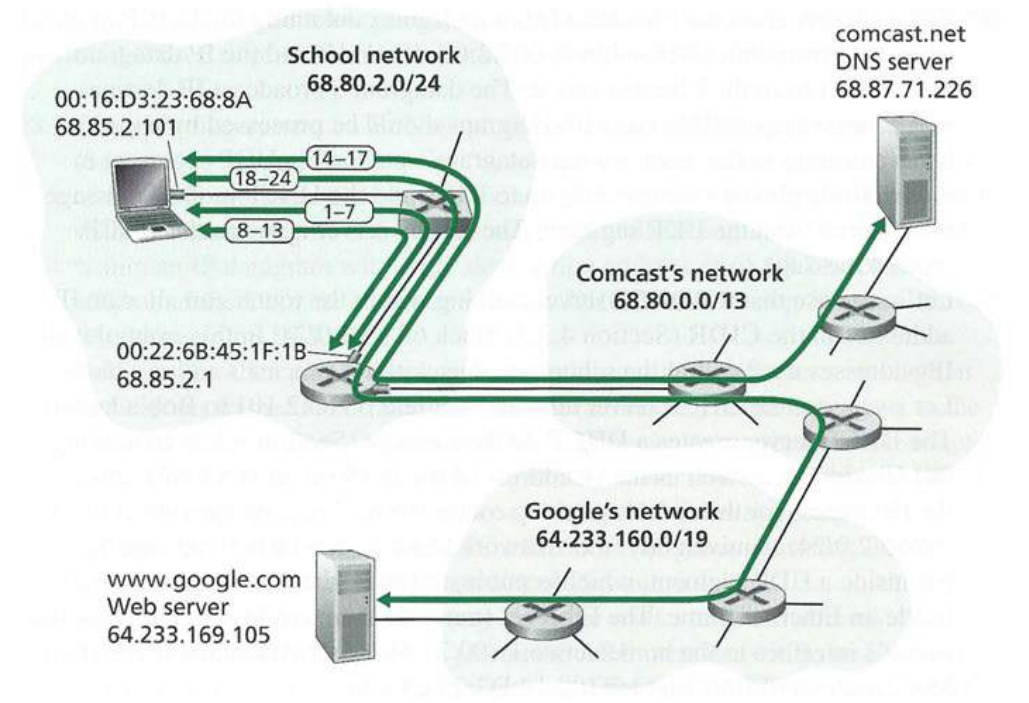
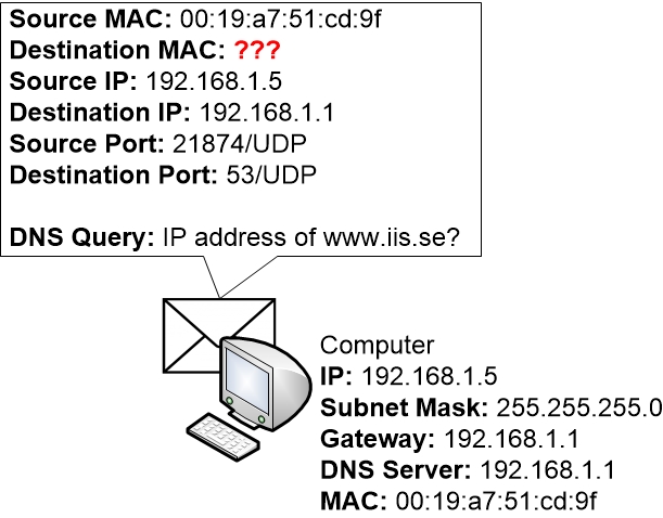
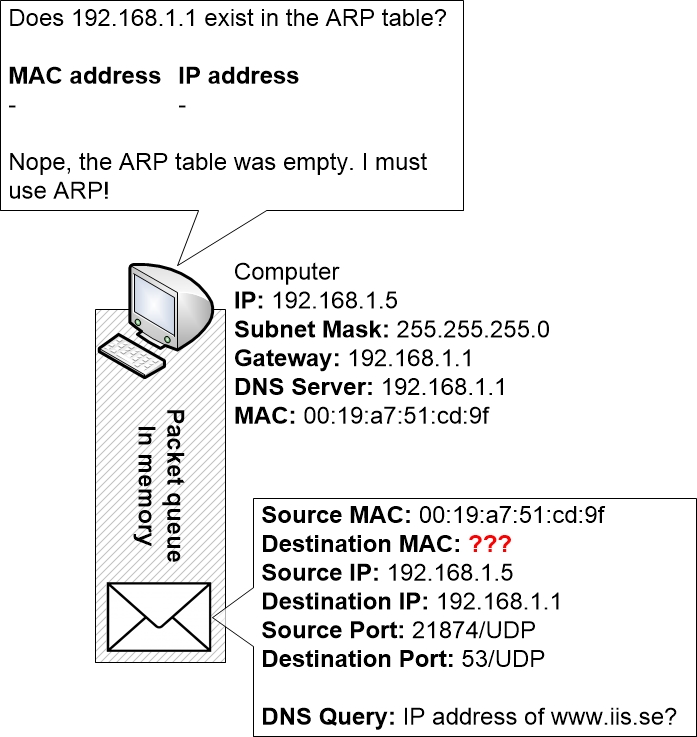
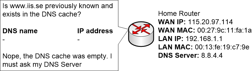
The operating system on Bob’s laptop thus creates a DNS query message, putting the string “www.google.com” in the question section of the DNS message.
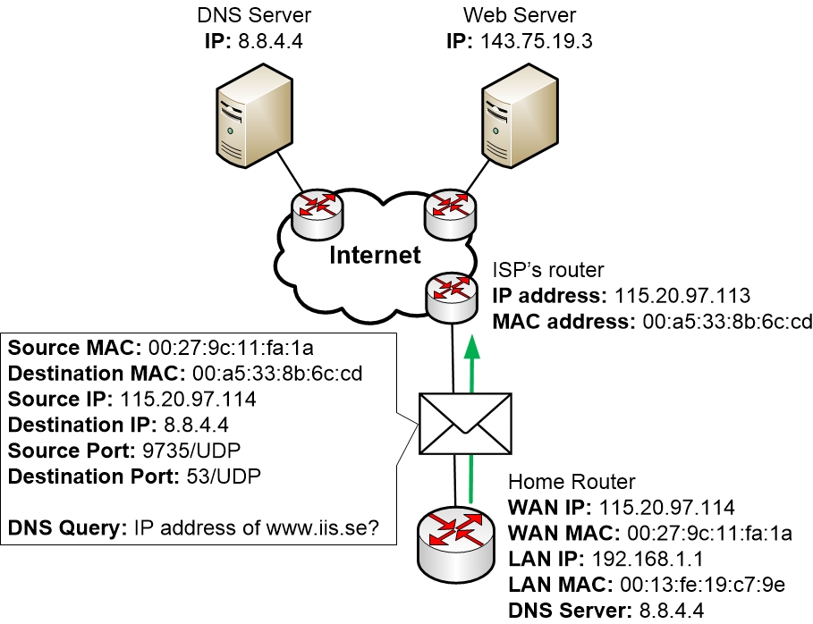
Bob’s laptop then places the datagram containing the DNS query message in an Ethernet frame.
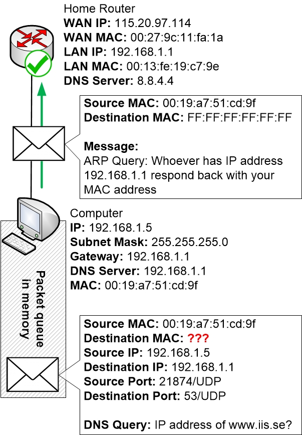
Bob’s laptop creates an ARP query message with a target IP address of 68.85.2.1 (the default gateway), places the ARP message within an Ethernet frame with a broadcast destination address (FF:FF:FF:FF:FF:FF) and sends the Ethernet frame to the switch, which delivers the frame to all connected devices, including the gateway router.
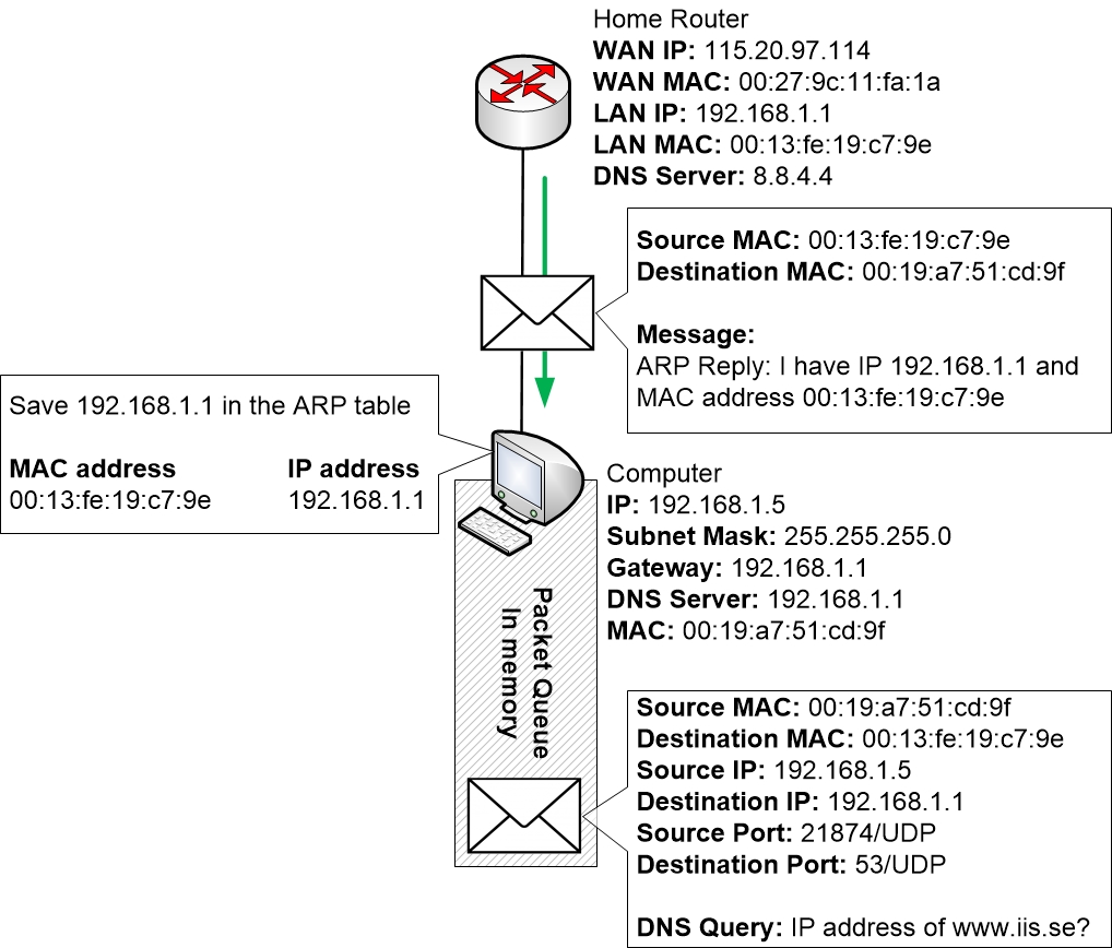
The gateway router receives the frame containing the ARP query message on the interface to the school network, and finds that the target IP address of 68.85.2.1 in the ARP message matches the IP address of its interface.
Bob’s laptop receives the frame containing the ARP reply message and extracts the MAC address of the gateway router (00:22:6B:45:1F:1B) from the ARP reply message.
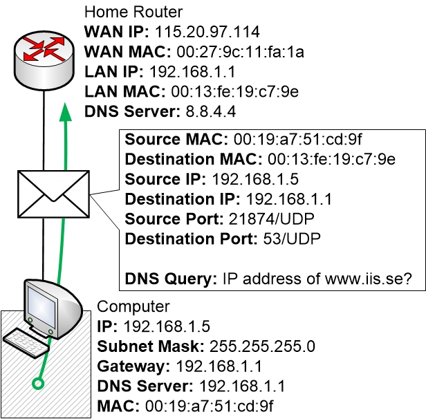
Bob’s laptop can now (finally!) address the Ethernet frame containing the DNS query to the gateway router’ s MAC address.
The gateway router receives the frame and extracts the IP datagram containing the DNS query.
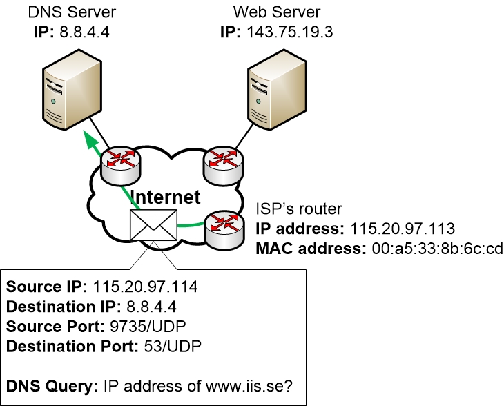
The leftmost router in the Comcast network receives the frame, extracts the IP datagram, examines the datagram’s destination address (68.87.71.226) and determines the outgoing interface on which to forward the datagram toward the DNS server from its forwarding table, which has been filled in by Comcast’s intra-domain protocol (such as RIP, OSPF or IS-IS) as well as the Internet’s inter-domain protocol, BGP.
Eventually the IP datagram containing the DNS query arrives at the DNS server.
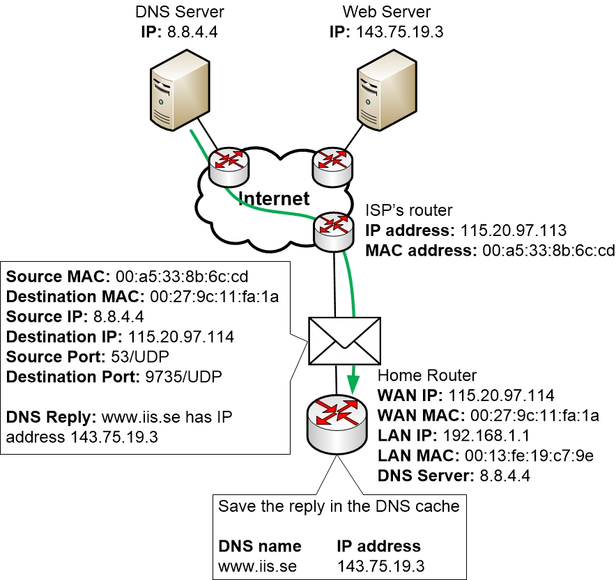
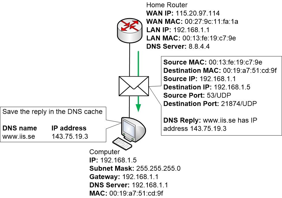
Bob’s laptop extracts the IP address of the server www.google.com from the DNS message.
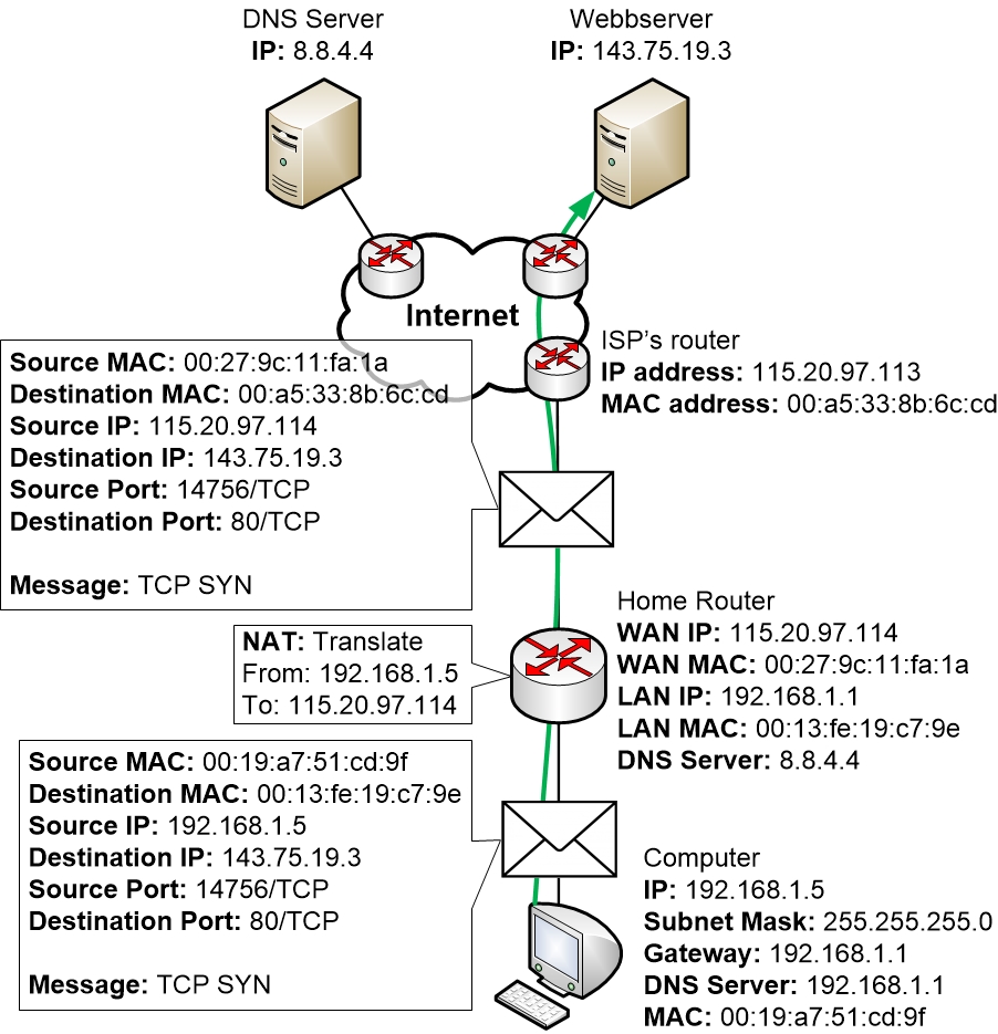
Now that Bob’s laptop has the IP address of www.google.com, it can create the TCP socket that will be used to send the HTTP GET message to www.google.com.
The routers in the school network, Comcast’s network, and Google’s network forward the datagram containing the TCP SYN toward www.google.com, using the forwarding table in each router, as in steps 14-16 above.
Eventually, the datagram containing the TCP SYN arrives at www.google.com.
The datagram containing the TCP SYN ACK segment is forwarded through the Google, Comcast, and school networks, eventually arriving at the Ethernet card in Bob’s laptop.
With the socket on Bob’s laptop now (finally!) ready to send bytes to www.google.com, Bob’ s browser creates the HTTP GET message containing the URL to be fetched.
The HTTP server at www.google.com reads the HTTP GET message from the TCP socket, creates an HTTP response message, places the requested Web page content in the body of the HTTP response message, and sends the message into the TCP socket.
The datagram containing the HTTP reply message is forwarded through the Google, Comcast, and school networks, and arrives at Bob’s laptop.