Previous: 00-Inspiration.html
document.querySelector('video').playbackRate = 1.2Our goal for today:
Get “feel” for big picture and terminology.
More depth, detail later in course.
Approach: use Internet as example.
Overview:
What is the Internet?
What is a protocol?
Network edge includes:
hosts, access net, physical media.
Network core includes:
packet/circuit switching, and Internet internal structure.
Performance matters, including:
loss, delay, throughput.
Ther are many protocol layers, service models.
Security is an afterthought?
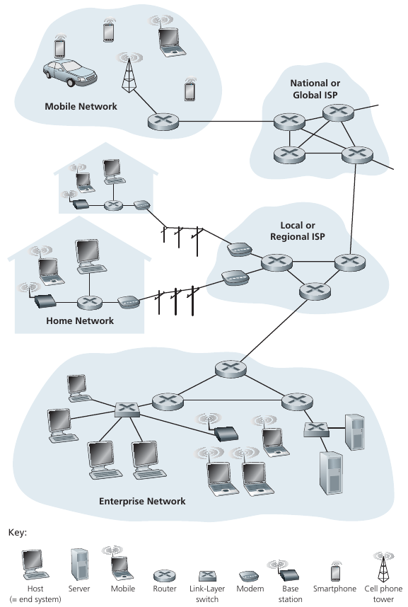
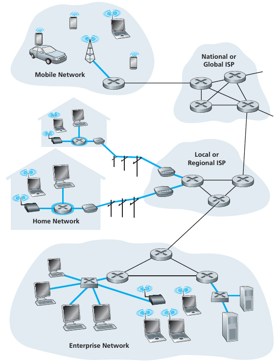
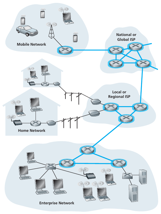
Billions of connected computing devices:
Hosts = end systems.
Hosts run network apps.
Smart devices run network apps.
Communication links:
Types include: Fiber, copper, radio, satellite, etc.
Transmission rate and timing is defined by bandwidth and latency.
Packet switches:
Routers and switches forward packets (chunks of data).
Inter-networked networks:
Many interconnected ISPs
Protocols:
Control sending, receiving of messages.
e.g., TCP, IP, HTTP, 802.11
Internet standards:
Public agreements about how to communicate.
RFC: Request for comments
IETF: Internet Engineering Task Force
Infrastructure that provides services to
applications:
Web, VoIP, email, games, e-commerce, social nets, …
Provides programming interface to apps:
Interfaces that allow application programs to “connect” to other hosts
on the Internet.
Provides service options, analogous to postal service.
What do you do if you accidentally interrupt someone?
What are some other human protocols?
A network protocol is similar to a human protocol,
except that the entities exchanging messages and taking actions,
are hardware or software components of some device.
For example, computer, smartphone, tablet, router, or other
network-capable device.
A protocol defines the format and the order of messages,
exchanged between two or more communicating entities,
as well as the actions taken on the transmission,
and/or receipt of a message or other event.
All communication activity in the Internet governed by
protocols,
public or proprietary.
Arrival order packet joke!
is critical to good a make
Network edge:
Hosts include clients and servers.
Servers are often in data centers.
Access networks, physical media:
Physical connections may be wired, wireless communication links,
etc.
Network core:
Interconnected routers in a bigger network of networks.
This is less visible to end users.
Hosts = end systems,
including BOTH clients and servers
Institutional routers = core!
Q: How to connect end systems to edge router?
Residential access networks,
Anstitutional access networks (school, company),
mobile access networks, etc.
Keep in mind:
Bandwidth (bits per second) of access network?
Latency (in miliseconds) of access network?
Shared or dedicated connection?
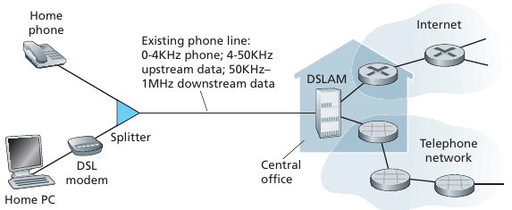
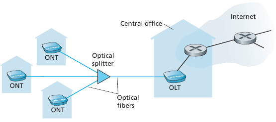
Uses existing telephone line to central office DSLAM.
Data over DSL phone line goes to Internet.
Voice over DSL phone line goes to telephone net.
< 2.5 Mbps upstream transmission rate (typically < 1 Mbps)
< 24 Mbps downstream transmission rate (typically < 10 Mbps)
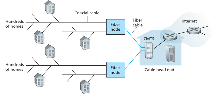
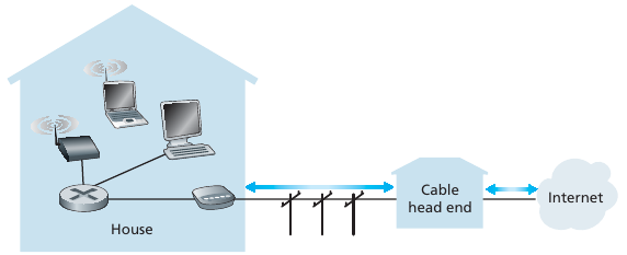
HFC: Hybrid Fiber Coax
Asymmetric:
up to 30Mbps downstream transmission rate,
2 Mbps upstream transmission rate.
Network of cable, fiber attaches homes to ISP router.
Homes share access network to cable head-end.
Unlike DSL, which has dedicated access to central office.
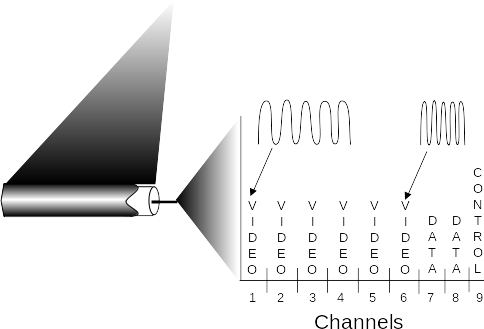
Frequency division multiplexing:
Different channels transmitted in different frequency bands.
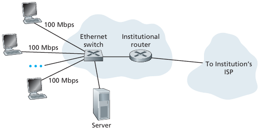
Typically used in companies, universities, etc.
Transmission rates range from 10 Mbps, 100Mbps, 1Gbps, 10Gbps, or
more.
Today, end systems typically connect into Ethernet switch.
Two uses of the term:
Shared wireless access
Network connects end system to router,
via base station aka “access point”.
Wide-area wireless access
Provided by telco (cellular) operator, 10’s km distance.
Bandwidth between 1 and 10 Mbps.
Technologies include: 3G, 4G, LTE, 5G, etc.
Computer networks are often classified in function of the geographical area that they cover
LAN : a local area network
interconnects hosts that are up to a few or maybe a few tens of
kilometers apart.
MAN : a metropolitan area network
interconnects devices that are up to a few hundred kilometers apart.
WAN : a wide area network
interconnects hosts that can be located anywhere on Earth.
Another classification of computer networks is based on their
physical topology.
In the following figures, physical links are represented as lines,
while boxes show computers or other types of networking equipment.

To allow any host to send messages to any other host in the
network,
the easiest solution is to organize them as a full-mesh,
with a direct and dedicated link between each pair of hosts.
Such a physical topology is sometimes used,
especially when high performance and high redundancy is required,
for a small number of hosts.
However, it has major drawbacks.
For a network containing n hosts,
each host must have n-1 physical interfaces.
The number of physical interfaces on a node limits the size of a
full-mesh network that can be built.

The second possible physical organization,
which is also used inside computers to connect different extension
cards,
is the bus.
In a bus network, all hosts are attached to a shared medium,
usually a cable through a single interface.
When one host sends an electrical signal on the bus,
the signal is received by all hosts attached to the bus.
A drawback of bus-based networks is that if the bus is physically
cut,
then the network is split into two isolated networks.
Bus-based networks are sometimes considered to be difficult to operate
and maintain,
especially when the cable is long and there are many places where it can
break.
Such a bus-based topology was used in early Ethernet networks.

A third organization of a computer network is a star topology.
In such topologies, hosts have a single physical interface,
and there is one physical link between each host and the center of the
star.
The node at the center of the star can be either:
a piece of equipment that amplifies an electrical signal, or
an active device, that understands the format of the messages exchanged
through the network.
Of course, the failure of the central node implies the failure of the
network.
However, if one physical link fails
(e.g. because the cable has been cut),
then only one node is disconnected from the network.
In practice, star-shaped networks are easier to operate and maintain
than bus-shaped networks.
Network administrators can control the network from a central
point.
Administered from a Web interface, or through a console-like
connection,
the center of the star is a useful point of control (enabling or
disabling devices)
and an excellent observation point (usage statistics).

A fourth physical organization of a network is the Ring topology.
Each host has a single physical interface connecting it to the
ring.
Any signal sent by a host on the ring will be received by all hosts
attached to the ring.
From a redundancy point of view, a single ring is not the best
solution,
as the signal only travels in one direction on the ring;
Thus if one of the links composing the ring is cut, the entire network
fails.
In practice, such rings have been used in local area networks,
but are now often replaced by star-shaped networks.
In metropolitan networks, rings are often used to interconnect multiple
locations.
In this case, two parallel links, composed of different cables,
are often used for redundancy.
With such a dual ring, when one ring fails,
all the traffic can be quickly switched to the other ring.

A fifth physical organization of a network is the tree.
Often used when a large number of customers must be connected in a very
cost-effective manner.
Cable TV networks are often organized as trees,
as are ethernet networks.

In practice, most real networks combine part of these topologies.
For example, a campus network can be organized as a ring between the key
buildings,
while smaller buildings are attached as a tree or a star to important
buildings.
An ISP network may have a full mesh of devices in the core of its
network,
and trees to connect remote users.
Bit:
propagates between transmitter/receiver pairs
Physical link:
what lies between transmitter & receiver
Guided media:
signals propagate in solid media: copper, fiber, coax
Unguided media:
signals propagate freely, e.g., radio
Coaxial cable:
Two concentric copper conductors
Bidirectional
Broadband: multiple channels on cable
Twisted pair (TP)
Two insulated copper wires
Category 5: 100 Mbps, 1 Gbps Ethernet
Category 6: 10Gbps
Fiber optic cable:
Glass fiber carrying light pulses, each pulse a bit
High-speed operation:
High-speed point-to-point transmission (e.g., 10’s-100’s Gbps
transmission rate)
Low error rate: repeaters spaced far apart
Immune to electromagnetic noise
Signal carried in electromagnetic spectrum
No physical “wire”
Bidirectional
Propagation environment effects:
Reflection
Obstruction by objects
Interference
Radio link types:
Terrestrial microwave
up to 45 Mbps channels
LAN (e.g., WiFi)
54 Mbps
Wide-area (e.g., cellular)
4G cellular: ~ 10 Mbps
Satellite
Kbps to 45Mbps channel (or multiple smaller channels)
270 msec end-end delay
Geosynchronous versus low altitude
Mesh of interconnected routers
Packet-switching:
Hosts break application-layer messages into packets.
Forward packets from one router to the next,
across links on path from source to destination.
Each packet transmitted at full link capacity.
Routing:
Determines source-destination route taken by packets.
A variety of routing algorithms exist.
Operates on longer time-scales.
Forwarding:
Move packets from router’s input to appropriate router output.
Chooses instant path of packet.
Ask:
Difference between routing and forwarding?
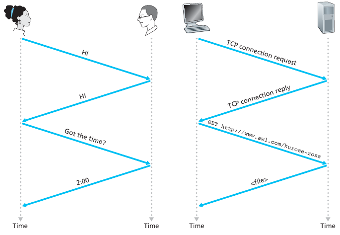
In a network application, end systems exchange messages with each
other.
Messages can contain anything the application designer wants.
Messages may perform a control function.
for example, the “Hi” messages in our handshaking example in or can
contain data,
such as an email message, a JPEG image, or an MP3 audio file.
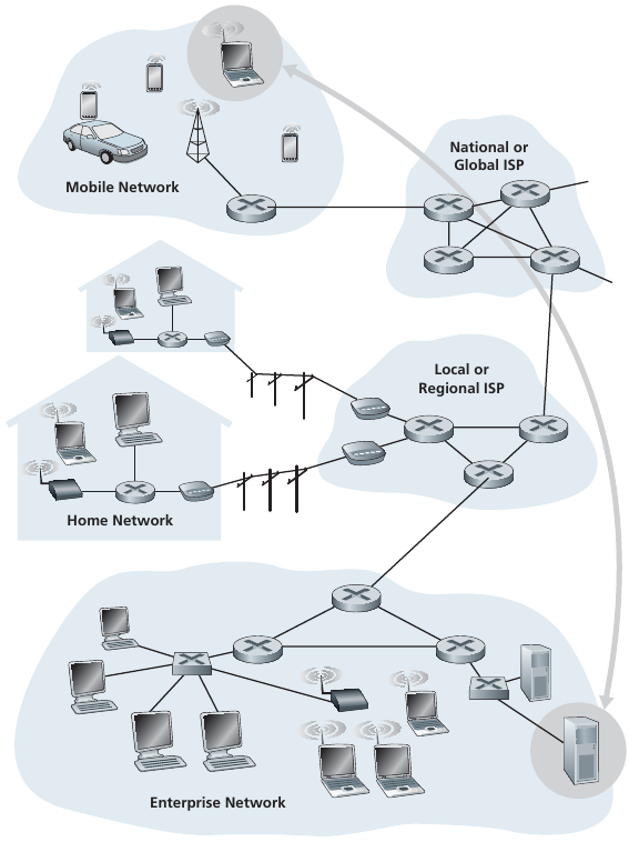
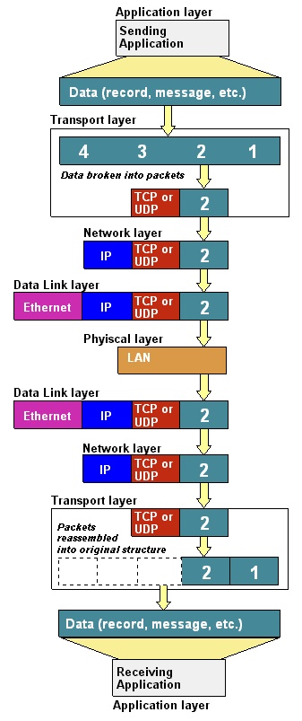
To send a message from a source end system to a destination end
system,
the source breaks long messages into smaller chunks of data known as
packets.
Between source and destination, each packet travels through
communication links and packet switches
(for which there are two predominant types, routers and link-layer
switches).
In TV and radio transmission, broadcast is often used.
Broadcasts send a video or radio signal to all receivers in a given
geographical area.
Broadcast is sometimes used in computer networks,
but only in local area networks where the number of recipients is
limited.
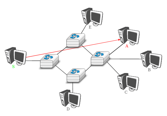
The first and most widespread transmission mode is called unicast.
In the unicast transmission mode, information is sent by one sender to
one receiver.
The example shows a network with two types of devices:
hosts (drawn as computers) and intermediate nodes (drawn as
cubes).
Hosts exchange information via the intermediate nodes.
In the example below, when host S uses unicast to send
information,
it sends it via three intermediate nodes.
Each of these nodes receives the information from its upstream node or
host,
then processes and forwards it to its downstream node or host.
This is called store and forward
We will see later that this concept is key in computer networks.
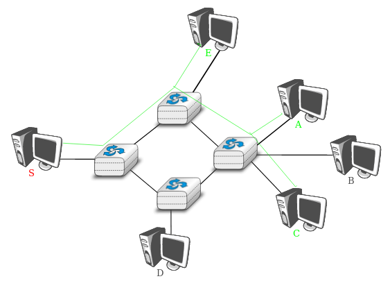
A second transmission mode is multicast transmission mode.
This mode is used when the same information must be sent to a set of
recipients.
It was first used in LANs but later became supported in wide area
networks.
When a sender uses multicast to send information to N receivers,
the sender sends a single copy of the information,
and the network nodes duplicate this information whenever
necessary,
so that it can reach all recipients belonging to the destination
group.
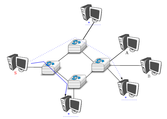
The last transmission mode is the anycast transmission mode.
It was initially defined in RFC 1542.
In this transmission mode, a set of receivers is identified.
When a source sends information towards this set of receivers,
the network ensures that the information is delivered to one receiver
that belongs to this set.
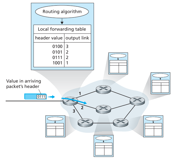
Every end system has an address called an IP address.
Source includes the destination’s IP address in the packet’s
header.
Address has a hierarchical structure.
Router examines a portion of the packet’s destination address,
and forwards the packet to best adjacent router.
Each router has a forwarding table that maps destination addresses
(or portions of the destination addresses) to that router’s outbound
links.
When a packet arrives at a router, the router:
examines the address, and searches its forwarding table,
using this destination address,
to find the appropriate outbound link.
Multiple routing protocols that are used,
to automatically develop the forwarding tables themselves.
They determine the shortest path from each router to each
destination,
and use the shortest path results to configure the forwarding tables in
the routers.
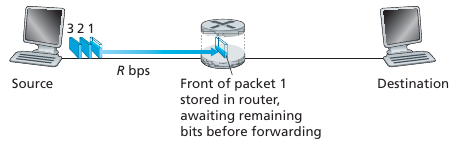
Takes L/R seconds to transmit (send out) L-bit packet into link at R
bps
Store and forward:
Entire packet must arrive at router before it can be transmitted on next
link.
End-end delay = 2L/R (assuming zero propagation delay)
One-hop numerical example:
L = 7.5 Mb
R = 1.5 Mb/s
One-hop transmission delay = 5 sec
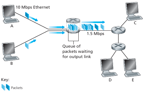
If arrival rate (in bits) to link exceeds transmission rate of link for
a period of time,
then packets will queue, wait to be transmitted on link.
Packets can be dropped (lost) if memory (buffer) fills up
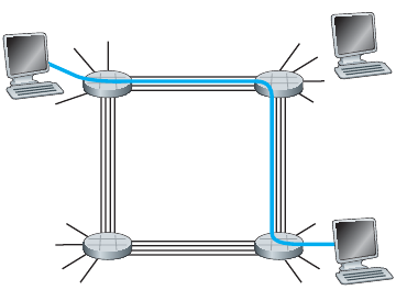
End-end resources allocated to, reserved for “call” between source &
destination:
In the diagram, each link has four circuits.
A call gets the 2nd circuit in top link, and the 1st circuit in right
link.
Dedicated resources: no sharing.
Circuit-like (guaranteed) performance.
Circuit segment idle if not used by call (no sharing).
Commonly used in traditional telephone networks.
How does this compare to packet switching?
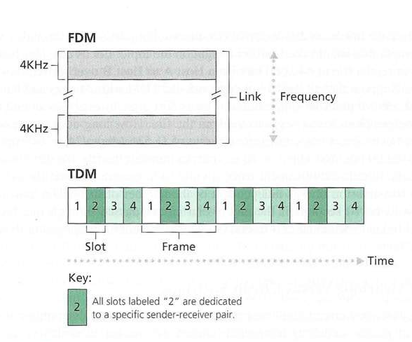
A circuit in a link is implemented with either:
Frequency-division multiplexing (FDM) or
Time-division multiplexing (TDM).
Example:
1 Mb/s link
each user:
100 kb/s when “active”
active 10% of time
circuit-switching:
10 users
packet switching:
with 35 users, probability > 10 active at same time is less than
.0004
Packet switching is great for:
bursty data, resource sharing.
It can be simpler, with no call setup (reserving a line).
Packet switching may be worse for:
Excessive congestion possible: packet delay and loss.
Protocols are needed for reliable data transfer, congestion control.
Q: How to provide circuit-like behavior?
Bandwidth guarantees needed for audio/video apps?
Still an unsolved problem
Q: human analogies of reserved resources (circuit switching) versus on-demand allocation (packet-switching)?
+++++++++++++ Cahoot-01-1
End systems connect to the Internet via access ISPs (Internet Service
Providers),
including residential, company, and university ISPs, etc.
Access ISPs in turn must be interconnected,
so that any two hosts can send packets to each other.
The resulting network of networks is very complex.
It’s evolution was driven by economics and national policies.
We’ll take a step-wise approach to describe current Internet
structure
Design considers not just technical considerations,
but also: corporate, historical, collusive, regulator
considerations.
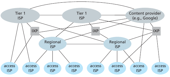
At center: small number of well-connected large networks.
“Tier-1” commercial ISPs (e.g., Level 3, Sprint, ATT, NTT), national and
international coverage
Content provider network (e.g., Google):
private network that connects it data centers to Internet, often
bypassing tier-1, regional ISPs
Internet Exchange Point (IXP) is a meeting point where multiple ISPs
can peer together.
An IXP is typically in a stand-alone building with its own
switches.
There well are over 400 IXPs in the Internet today (when this was
written).
Review the edges/paths above.
++++++++++++++ Cahoot-01-2
How does loss and delay occur?
Packets queue in router buffers
packet arrival rate to link (temporarily) exceeds output link
capacity
packets queue, wait for turn
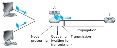
All delay is not the same.
If we let:
d_proc, d_queue, d_trans, and d_prop denote the:
processing, queuing, transmission, and propagation delays,
then the total nodal delay is given by:
d_nodal = d_proc + d_queue + d_trans + d_prop
Network load
The impact of increasing network load is super-linear over delay.
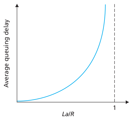
R: link bandwidth (bps)
L: packet length (bits)
a: average packet arrival rate
La/R ~ 0: avg. queueing delay small
La/R -> 1: avg. queueing delay large
La/R > 1: more “work” arriving than can be serviced, average delay
infinite!
The traceroute program provides delay
measurements,
from source to router, along end-end Internet path towards
destination.
For all i:
    Sends three packets that will reach router i on path towards destination.
    Router i will return packets to sender.
Sender times interval between transmission and reply.(watch with Wireshark too):
$ traceroute mst.edu
$ traceroute www.mst.edu
$ traceroute efpl.ch
$ traceroute www.epfl.ch
No response:
3 independent delays measured (triplicate redundant measurements)
Alternative fancier program:
$ mtr epfl.ch
With no place to store such a packet, a router will drop that
packet;
that is, the packet will be lost.
In addition to delay and packet loss,
another critical performance measure in computer networks is end-to-end
throughput.
To define throughput, consider transferring a large file,
from Host A to Host B, across a computer network.
This transfer might be, for example,
a large video clip from one peer to another in a P2P file sharing
system.
The instantaneous throughput at any instant of time is:
the rate (in bits/sec) at which Host B is receiving the file.
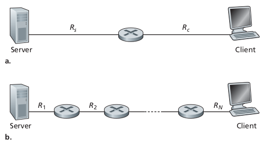
These could reasonably often have the same throughput, but which likely
has worse delay?
Bottleneck throughput limitations tend to be servers and local ISPs
(edge), not the backbone (core).
Networks are complex, with many “pieces”:
hosts
routers
links of various media
applications
protocols
hardware, software
Question:
Is there any hope of organizing structure of such a network?
Or at least our discussion of networks?
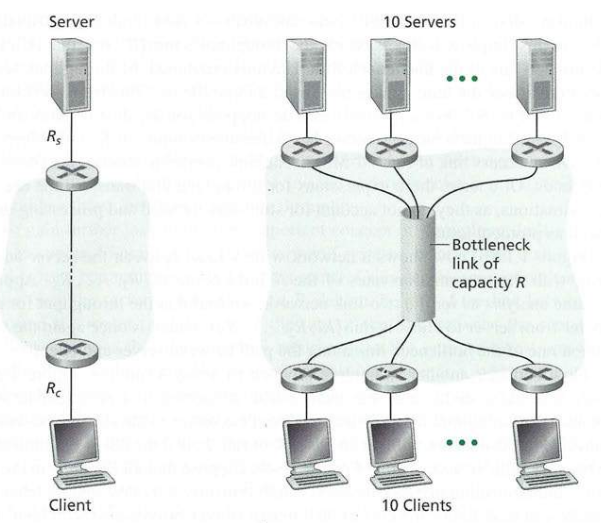
Analogy: horizontal layering of airline functionality
Layers:
Each layer implements a service,
via its own internal-layer actions,
relying on services provided by layer below.
To provide structure to the design of network protocols, network
designers organize protocols,
and the network hardware and software that implement the protocols, in
layers.
In a theoretical vacuum, each protocol belongs to one of the
layers,
just as each function in the airline architecture.
A protocol layer can be implemented in software, in hardware,
or in a combination of the two.
When taken together, the protocols of the various layers define a
networking protocol stack.
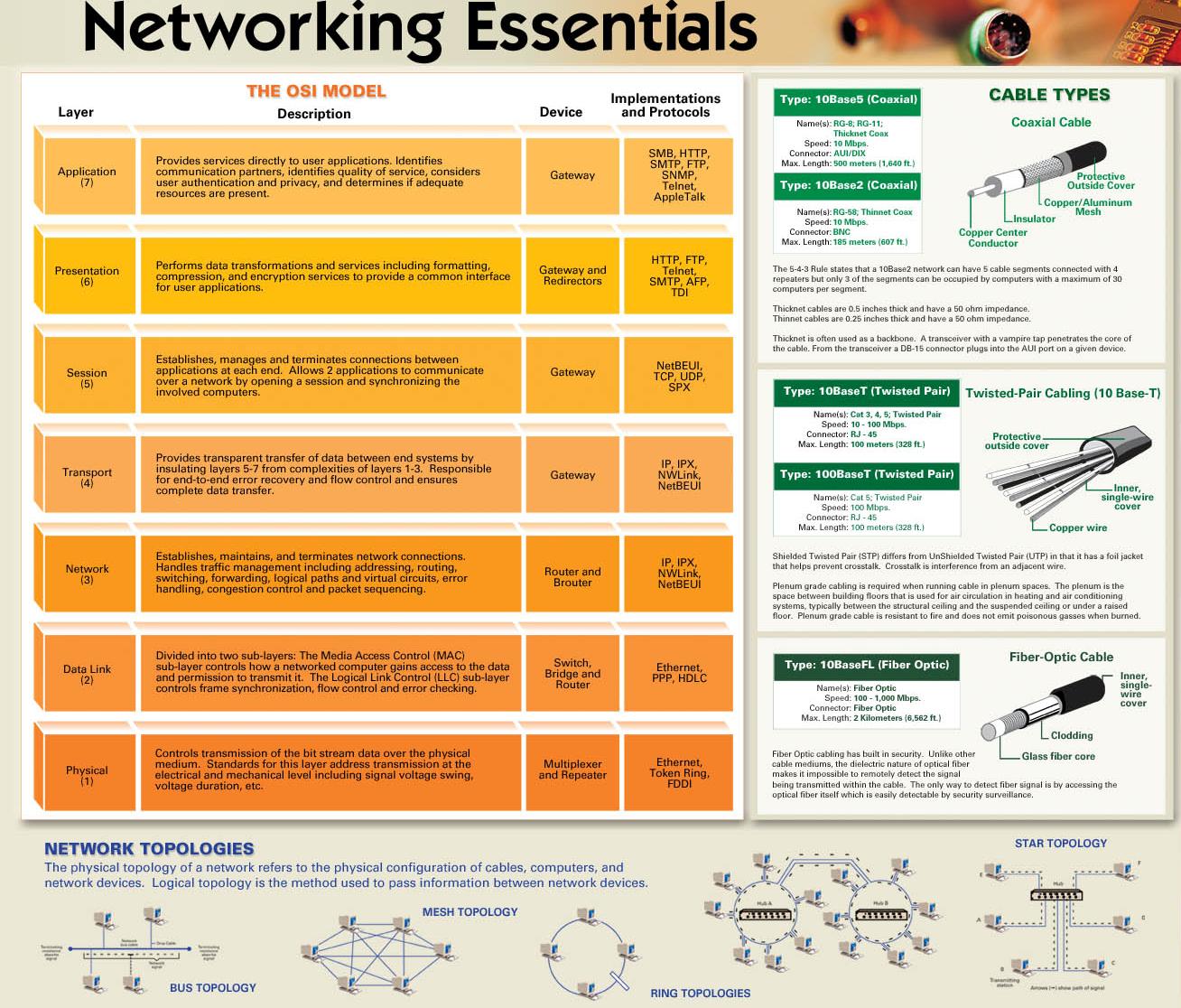
The Internet protocol stack can be oversimplified to five
layers:
1. physical,
2. link,
3. network,
4. transport,
5. application
Why layering?
Explicit structure allows identification, relationship of complex
system’s pieces.
Modularity eases maintenance, updating of system.
Change of implementation of layer’s service transparent to rest of
system.
For example, a change in gate procedure doesn’t affect rest of
system.
Layering considered harmful?
Internet protocol stack
Application:
supporting network applications
FTP, SMTP, HTTP
Transport:
OS-process to OS-process data transfer
TCP, UDP, and some more rare others
Network:
routing of datagrams from source to destination
IP, routing protocols
Link:
data transfer between neighboring network elements
Ethernet, 802.111 (WiFi), PPP, etc.
Physical:
bits “on the wire” or “over the airwaves”
Supporting network applications
Network applications and their application-layer protocols reside
here
Examples:
HTTP Hypertext Transfer Protocol provides for
Web,
including document request and transfer (example Wireshark http://httpforever.com/)
SMTP Simple Mail Transfer Protocol provides for the transfer of e-mail messages
FTP (which provides for the transfer of files between two end systems).
DNS provides translation of human-friendly names for
Internet end systems,
like https://www.ietf.org
to a 32-bit network address (ipv4).
This is also done with the help of a specific application-layer
protocol,
namely, the Domain Name System (DNS).
An application-layer protocol is distributed over multiple end
systems,
with the application in one end system using the protocol,
to exchange packets of information with the application in another end
system.
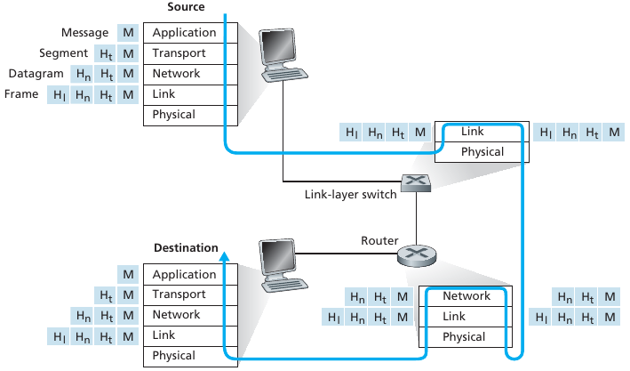
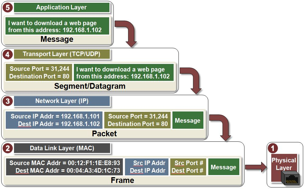
Packet of information at application layer is a
message.
Encryption often implemented at this layer
(though it should at least as low as the Network/IP-layer).
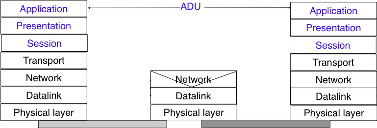
The upper layer of our architecture is the Application layer.
This layer includes all the mechanisms and data structures that are
necessary for the applications.
Our big-picture book calls these packets ADUs.

OS-Process to OS-process data transfer
Transports application-layer messages between application
endpoints
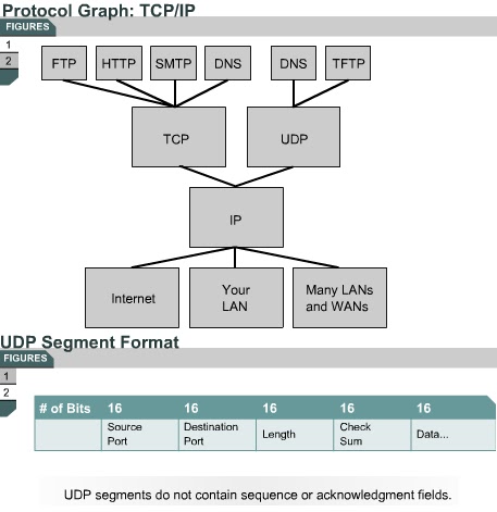
In the current Internet, there are two primary transport
protocols,
TCP and UDP, either of which can transport application-layer
messages.
TCP (Transmission Control Protocol) provides a
connection-oriented service to its applications.
Guaranteed delivery of application-layer messages to the
destination
Flow control (that is, sender/receiver speed matching).
Congestion-control mechanism: a source throttles its transmission rate
when the network is congested.
UDP (User Datagram Protocol) protocol provides a
connectionless service to its applications.
No-frills service that provides no reliability, no flow control, and no
congestion control.
Transport-layer packet is a segment.
Most realizations of the network layer (below), including the
internet,
do not provide a reliable service.
However, many applications need to exchange information reliably,
and so using the network layer service directly would be very difficult
for them.
Ensuring the reliable delivery of the data produced by applications is
the task of the transport layer.
Transport layer entities exchange segments.
A segment is a finite sequence of bytes that are transported inside one
or more packets.
A transport layer entity issues segments (or sometimes part of segments)
as requests to the underlying network layer entity.
The most widely used transport layers on the Internet are:
TCP, that provides a reliable connection-oriented bytestream transport
service, and
UDP ,that provides an unreliable connection-less transport
service.
There are some other interesting transport layer protocols, though they
are not as common.

04-NetworkData.html
06-NetworkControl.html
Routing of datagrams from source to
destination
Responsible for moving network-layer packets known as
datagrams from one host to another.
Transport-layer protocol (TCP or UDP) from source host passes both a
transport-layer segment and a destination address to the network
layer.
Network layer then provides the service of delivering the segment to the
transport layer in the destination host.
Network layer includes the celebrated IP,
which defines the fields in the datagram,
as well as how the end systems and routers act on these fields.
There is only one IP protocol (or two…),
and all Internet components that have a network layer must run it.
Network layer also contains many routing protocols that determine the
routes
The network layer is built above the datalink layer.
The Datalink layer (below) allows directly connected hosts to exchange
information,
but it is often necessary to exchange information between remote
hosts,
that are not attached to the same physical medium.
This is the task of the network layer.
Network layer entities exchange packets.
A packet is a finite sequence of bytes that is transported by the
datalink layer inside one or more frames.
A packet usually contains information about its origin and its
destination,
and usually passes through several intermediate devices called
routers,
on its way from its origin to its destination.

07-DataLink.html
08-Wireless.html
Data transfer between adjacent nodes
At each node, the network layer passes the datagram down to the link
layer,
which delivers the datagram to the next node along the route.
At this next node, the link layer passes the datagram up to the network
layer.
Some link-layer protocols provide reliable delivery, from transmitting
node, over one link, to receiving node.
Examples of link-layer protocols include: Ethernet, WiFi, the cable
access network’s DOCSIS protocol, and more
A datagram may be handled by Ethernet on one link and by Wifi on the
next link.
The network layer (above) will receive a different service from each of
the different link-layer protocols.
link-layer packets are frames.
The Datalink layer builds on the service provided by the underlying
physical layer.
The Datalink layer allows two hosts that are directly connected through
the physical layer to exchange information.
The unit of information exchanged between two entities in the Datalink
layer is a frame.
A frame is a finite sequence of bits.
Some Datalink layers use variable-length frames while others only use
fixed-length frames.
Some Datalink layers provide a connection-oriented service while others
provide a connectionless service.
Some Datalink layers provide reliable delivery while others do not
guarantee the correct delivery of the information.
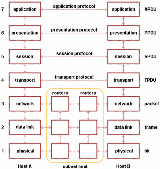
An important point to note about the Datalink layer is that,
although the figure below indicates that two entities of the Datalink
layer exchange frames directly,
in reality this is slightly different.
When the Datalink layer entity on the left needs to transmit a
frame,
it issues as many requests to the underlying physical layer as there are
bits in the frame.
The physical layer will then convert the sequence of bits in an
electromagnetic or optical signal,
that will be sent over the physical medium.
The physical layer on the right hand side of the figure will decode the
received signal,
recover the bits and issue the corresponding Data.indication primitives
to its Datalink layer entity.
If there are no transmission errors, this entity will receive the frame
sent earlier.

Bits “on the wire”
The protocols in this layer are again link dependent and further depend
on the actual transmission medium of the link
(for example, twisted-pair copper wire, single-mode fiber optics).
For example, Ethernet has many physical-layer protocols: one for
twisted-pair copper wire,
another for coaxial cable, another for fiber, and so on.
In each case, a bit is moved across the link in a
different way.
An important point to note about the Physical layer is the service
that it provides.
This service is usually an unreliable connection-oriented service that
allows the users of the Physical layer to exchange bits.
The unit of information transfer in the Physical layer is the bit.
The physical layer service is unreliable because:
the physical layer may change, e.g. due to electromagnetic
interferences, the value of a bit being transmitted,
the physical layer may deliver more bits to the receiver than the bits
sent by the sender, and
the physical layer may deliver fewer bits to the receiver than the bits
sent by the sender.
The physical layer allows thus two or more entities that are directly
attached to the same transmission medium to exchange bits.
Being able to exchange bits is important as virtually any information
can be encoded as a sequence of bits.
Electrical engineers are used to processing streams of bits,
but computer scientists usually prefer to deal with higher level
concepts.

Ask:
Does a packet go through all the layers in edge and the core?
What happens when the core meddles in layers higher than it is intended
to?
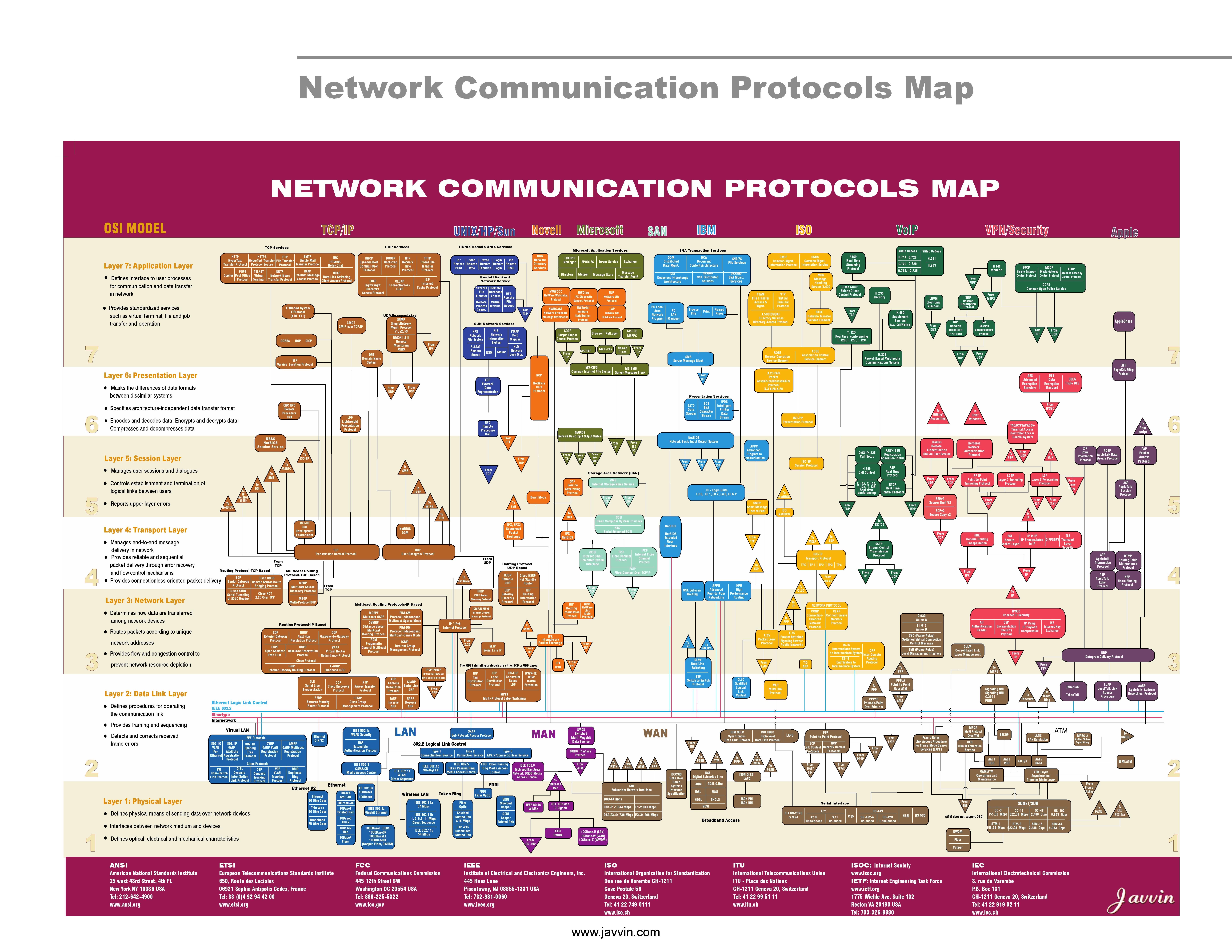
IP vs. OSI stacks
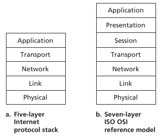
ISO/OSI reference model extras
Presentation: allow applications to interpret
meaning of data, e.g., encryption, compression, machine-specific
conventions
Session: synchronization, checkpointing, recovery of
data exchange
Internet stack “missing” these layers.
These services, if needed, must be implemented in application.
Are they needed?
Most people talk about the OSI model as having 7
layers,
but they don’t mention layer 8, where most of the problems
actually occur…
Ask: What is layer 8??
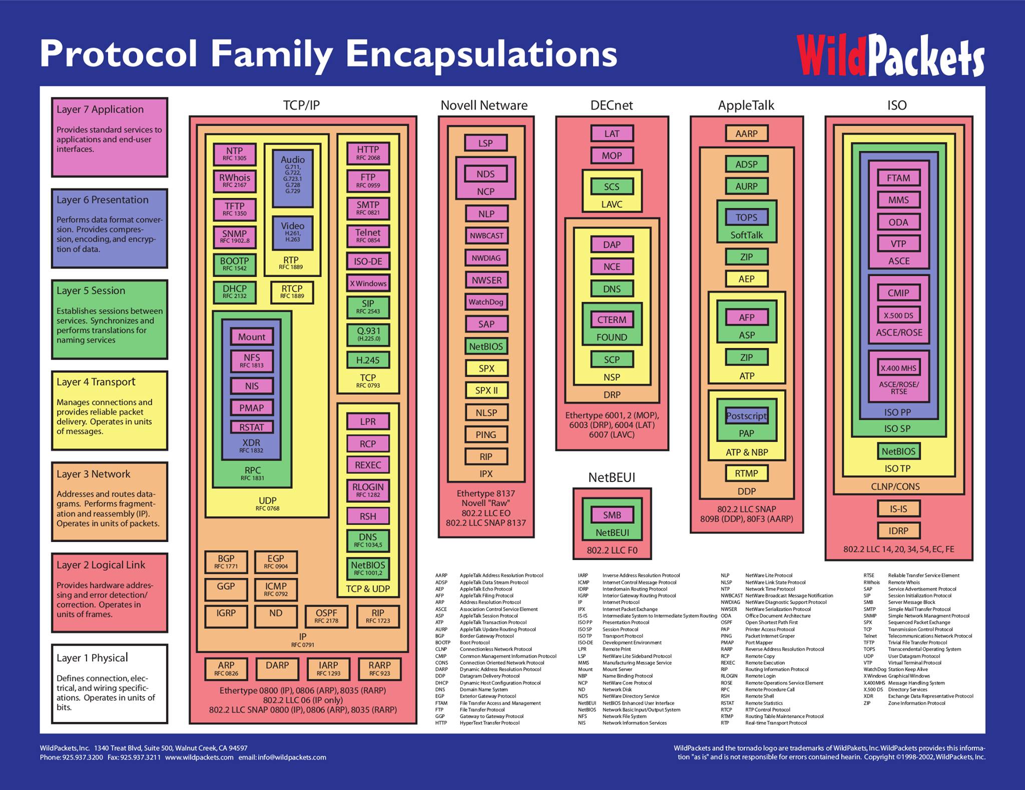
Actual graph/tree of protocols
Application on top

Physical on the bottom
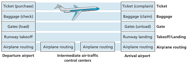
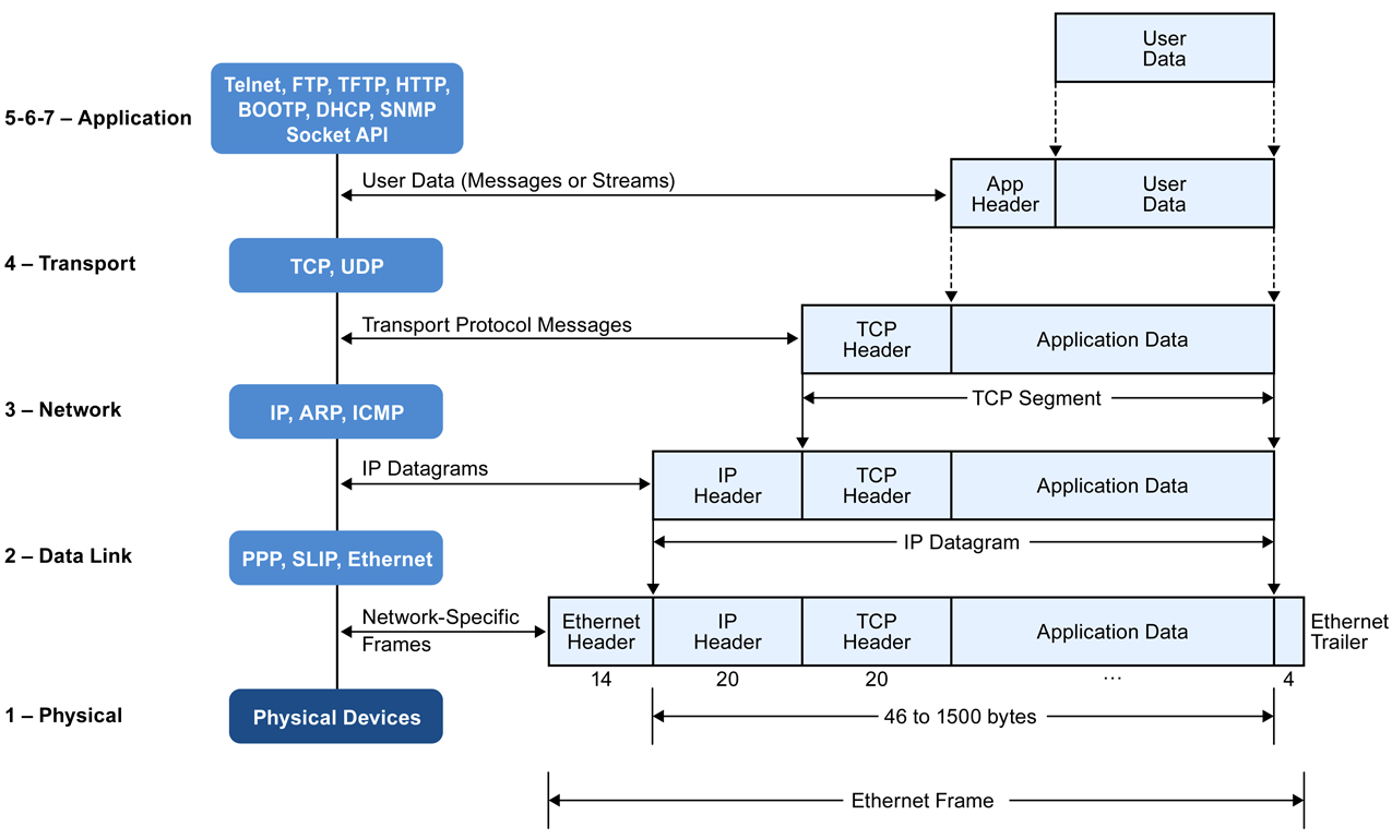
Encapsulating packets
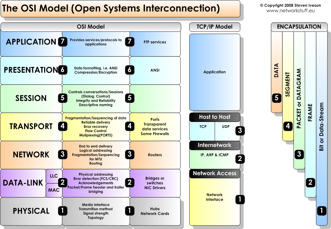
TCP/IP suite
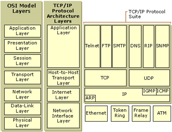
Left two are theoretical, while right is closer to the actual
system.
TCP/IP vs. OSI
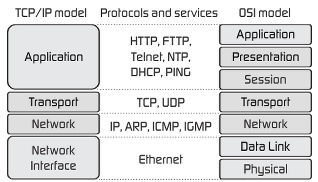
OSI levels
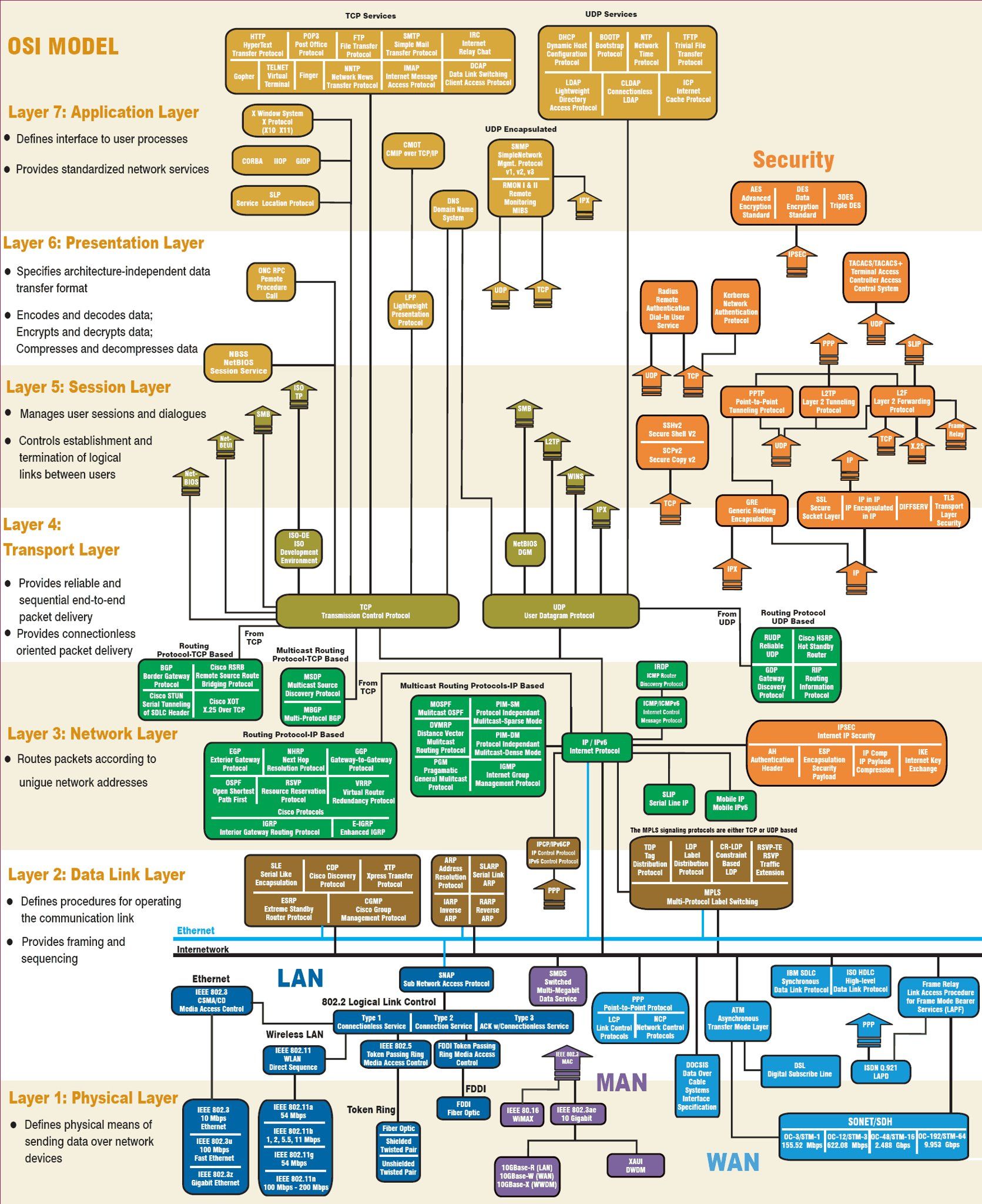
++++++++++++++ Cahoot-01-3
In this graph, what is most central?
What is hardest to change?
What is easiest to innovate with?
Tunneling here is a very interesting way to visualize network
protocol interactions.
In some ways, this is the best way to make such a diagram:
+++++++++++++++++++ Cahoot-01-4
Internet not originally designed with (much) security in mind
Original vision: “a group of mutually trusting users attached to a
transparent network”
Internet protocol designers playing “catch-up”
Security considerations in all layers!
Field of network security:
how bad actors can attack computer networks,
how we can defend networks against attacks,
how to design architectures that are immune to attacks.
DoS (Denial of Service) - the most common attack, often easy
Packet “sniffing”:
broadcast media (shared Ethernet, wireless),
promiscuous network interface reads/records all packets (including
passwords!) that are passing by.
Masquerading using faked identity,
and more!
Why is enumeration part of attacks?
What software is the target running?
Might it be vulnerable?
Are there any holes?
Demo:
# which ports are open?
nmap mst.edu
nmap epfl.ch
nmap www.epfl.ch
# Look at headers:
curl --head info.cern.ch
wget --server-response info.cern.chMalware can get into host from:
Virus: self-replicating infection by receiving/executing object (e.g.,
e-mail attachment)
Worm: self-replicating infection by passively receiving object that gets
itself executed
Spyware malware can record keystrokes, web sites visited, upload info
to collection site
Infected host can be enrolled in botnet, used for spam. DDoS attacks
Denial of Service (DoS): attackers make resources (server, bandwidth)
unavailable to legitimate traffic,
by overwhelming resource with bogus traffic
DDoS
packet “sniffing”:
broadcast media (shared Ethernet, wireless)
promiscuous network interface reads/records all packets (e.g., including
passwords!) passing by
Wireshark software is a packet sniffer
Malicious infrastructure.
A trustless “Distrust the infrastructure” is a good policy, even when
you don’t think it’s corrupt.
IP spoofing: send packet with false source address
Next: 02-Application.html