Tip: If anyone want to speed up the lecture videos a little, inspect
the page, go to the browser console, and paste this in:
document.querySelector('video').playbackRate = 1.2
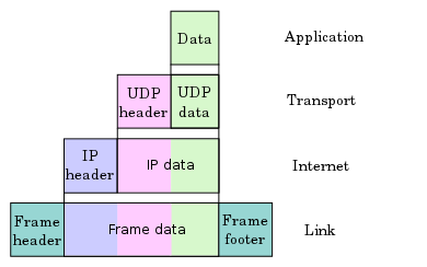
Previous-Previous: Application headers (data from this
perspective) Previous: transport header (Example is UDP in diagram,
but could be TCP) Now: IP header Next: Data link framing Next-Next: Physical layer
1.4.1 Scope
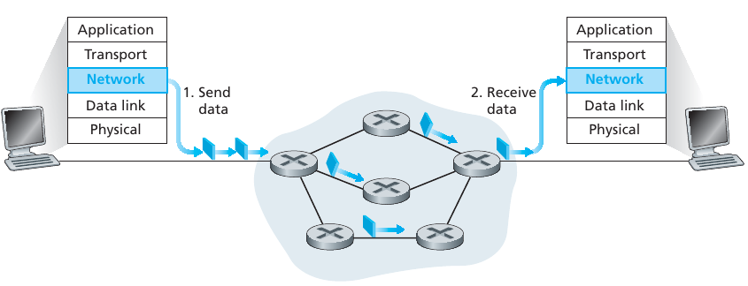
Data from the transport layer above is passed to network layer.
Reminder: TCP and UDP had source IP and destination IP in checksum
pseudo-header.
Network layer is hard to upgrade or change (it’s everywhere)!
Goal: to transport segment from sending to receiving
host
On sending side, encapsulates segments into
datagrams
On receiving side, process datagrams, and then deliver segments to
transport layer
Network layer protocols exist in every host and router.
Routers examine header fields in all IP datagrams passing through,
potentially re-writing and editing them.
1.4.1.1 Forwarding and routing
Role of the network layer is simple, to move packets from a sending
host to a receiving host.
Two important network-layer functions can be identified:
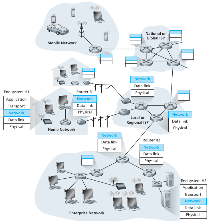
1.4.1.1.1 1. Forwarding
When a packet arrives at a router’s input link, the router must move
the packet to the appropriate output link.
For example, a packet arriving from Host H1 to Router R1 must be
forwarded to the next router on a path to H2.
This is a fast, momentary “decision” about where to launch the
packet.
The decision is made by consulting a pre-computed table.
04-NetworkData/kurose_ch4_01.png
1.4.1.1.2 2. Routing
The network layer must also build the tables used by the forwarding
step.
This table determines the route, or path taken by packets, as they
flow from a sender to a receiver.
The algorithms that calculate these paths are referred to as routing
algorithms.
A routing algorithm would use network graph information to determine
these tables, and thus, a path along which packets flow from Host1 to
Host2.
+++++++++++++++++++++ Cahoot-04-1
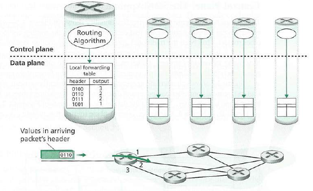
1.4.1.2 Data plane and control
plane
We divide the network layer based on these functions.
1.4.1.2.1 Data plane
local, per-router function
determines how datagram arriving on router input port is forwarded
to router output port
forwarding function
1.4.1.2.2 Control plane
network-wide logic
determines how datagram is routed among routers along end-end path
from source host to destination host
two control-plane approaches:
traditional routing algorithms: implemented in
routers
software-defined networking (SDN): implemented in
(remote) servers
+++++++++++++++++++++ Cahoot-04-2
1.4.2 Preview: Link interface (next
layer down)
A quick forward-reference:
ARP (Address Resolution Protocol) queries use a know IP address to
lookup a MAC address (link layer address),
so that a switch (data-link layer 2 device that routes based on MAC
address) can send directly to an interface by saying:
“Hey all on the mac layer, whoever has this IP address, what is their
MAC address?”
1.4.3 IPv4 address (more to come
below)
04-NetworkData/IPv4_address.png
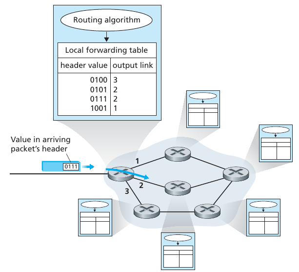
1.4.4 Routing algorithms build
forwarding tables
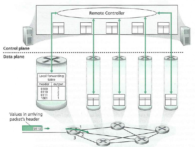
Every router has a forwarding table.
A router forwards a packet by examining the value of the IP field in the
arriving packet’s header,
and then using this header value to index into the router’s forwarding
table.
The value stored in the forwarding table entry for that header indicates
the router’s outgoing link interface,
to which that packet is to be forwarded.
Note: the diagram immediately below is idealized to have a short bit
chunk, but the principles are the same for real IP addresses:
Routing sets up these forwarding tables.
The routing algorithm to determine tables may be centralized (e.g., with
an algorithm executing on a central site and downloading routing
information to each of the routers) or decentralized (i.e., with a piece
of the distributed routing algorithm running in each router).
In either case, a router receives routing protocol messages, which are
used to configure its forwarding table.
1.4.4.1 Classic vs. Software
defined network (SDN)
1.4.4.1.1 Classic
Individual routing algorithm components in each and every router
interact in the control plane.
1.4.4.1.2 SDN
A distinct (typically remote) controller interacts with local control
agents (CAs).
1.4.5 Datagram networks
In a datagram network, each time an end system wants to send a packet,
it stamps the packet with the address of the destination end system, and
then pops the packet into the network.
1.4.5.1 Datagram packet
routing
As a packet is transmitted from source to destination, it passes
through a series of routers.
Each of these routers uses the packet’s destination IP address to
forward the packet.
Specifically, each router has a forwarding table that maps
destination IP addresses to link interfaces
Consider the network interface card (NIC) in your computer.
When a packet arrives at a router, that router uses the packet’s
destination IP address to look up the appropriate output link interface
in the forwarding table.
The router then forwards the packet to that output link
interface.
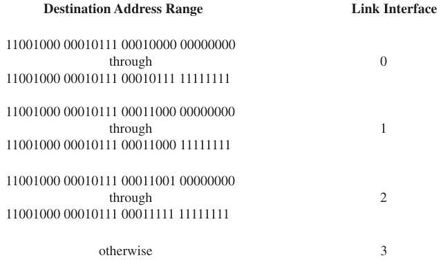
1.4.5.2 Routing tables
Suppose that our router has four links, numbered 0 through 3, and
that packets are to be forwarded to the link interfaces as
follows:
Important points to ponder:
If IP addresses are sold in blocks, where might ranges end up,
geographically?
If ranges of addresses are re-sold, where might they end up?
Why can a match in the routing table be shorter than an IP address
itself?
Why should it be?
Why do we match the longest prefix?
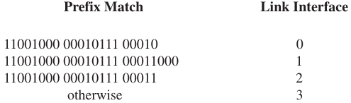
1.4.5.2.1 Longest prefix match
When there are multiple matches, the router uses the longest prefix
matching rule.
That is, it finds the longest matching entry in the table and forwards
the packet to the link interface associated with the longest prefix
match.
+++++++++++++++++++++ Cahoot-04-3
1.5 Router internals
Router architecture
Routing and management functions are collectively referred to as the
router control plane.
Control plane is usually implemented in software, and executes on
the routing processor (typically a traditional CPU)
Millisecond time range:
04-NetworkData/kurose_ch4_05.png
Forwarding functions are collectively referred to as the router
forwarding plane.
Often implemented in application-specific hardware.
Nanosecond time range
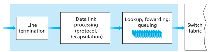
1.5.1 Input ports
04-NetworkData/kurose_ch4_05.png
Inputs are a physical layer function, terminating an incoming
physical link
Link-layer functions needed to interoperate with the link layer at
the incoming link.
Lookup function is also performed at the input port.
This will occur in the rightmost box of the input port.
It is here that the forwarding table is consulted to determine the
router output port to which an arriving data packet will be forwarded
via the switching fabric to an output port.
On the other hand, control packets, carrying routing protocol
information, are forwarded from an input port to the routing
processor.
The term port here, is referring to the physical input and output
router interfaces, is different from the software ports associated with
network applications and sockets.
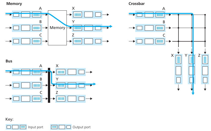
1.5.2 Switching fabric
The switching fabric connects the router’s input ports to its output
ports.
This switching fabric is completely contained within the router,
a network inside of a network router!
1.5.3 Output ports
04-NetworkData/kurose_ch4_05.png
Stores packets received from the switching fabric and transmits
these packets on the outgoing link by performing the necessary
link-layer to physical-layer functions.
When a link is bidirectional (that is, carries traffic in both
directions), an output port will typically be paired with the input port
for that link
Buffering is required when datagrams arrive from the switch fabric
faster than the output transmission rate.
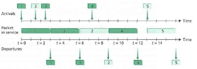
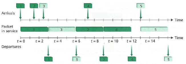
“Scheduling discipline” chooses among queued datagrams for
transmission:
FIFO (first in first out)
Priority queue (could be pay $, think net neutrality)
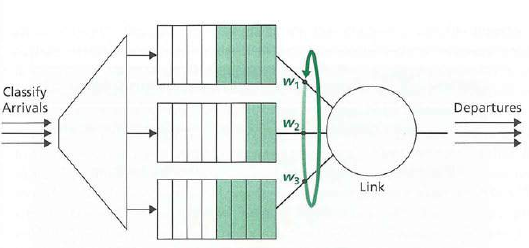
Round robin (rotating queue)
Weighted fair queuing (WFQ)
If queues are full, Datagram (packets) can be lost due to
congestion, lack of buffers.
Priority scheduling: who gets best performance, network
neutrality?
1.5.4 Routing processor
The routing processor executes the routing protocols,
maintains routing tables and attached link state information,
and computes the forwarding table for the router.
It also performs the network management functions.
1.5.5 Input processing
The lookup performed in the input port is central to the router’s
operation.
It is here that the router uses the forwarding table, to look up the
output port,
to which an arriving packet will be forwarded via the switching
fabric.
The forwarding table is computed and updated by the routing
processor,
with a shadow copy typically stored at each input port.
Each input port searches through the forwarding table looking for the
longest prefix match
Once a packet’s output port has been determined via the lookup,
the packet can be sent into the switching fabric.
04-NetworkData/kurose_ch4_06.png
1.5.6 Switching
Switching architecture variations:
Which is fastest?
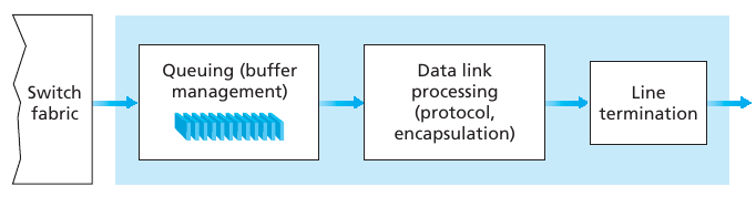
1.5.7 Output processing
Takes packets that have been stored in the output port’s memory and
transmits them over the output link.
This includes selecting and de-queueing packets for transmission,
and performing the needed link-layer to physical-layer transmission
functions.
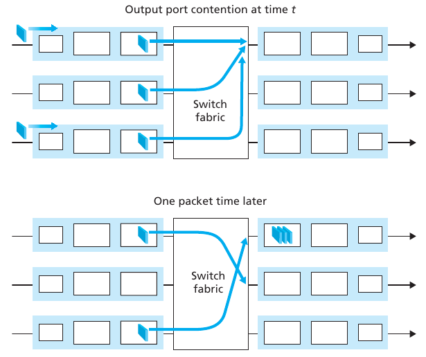
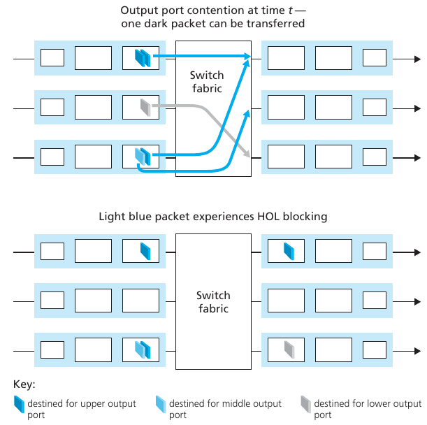
1.5.8 Queuing
As queues grow large, the router’s memory can eventually be exhausted
and packet loss will occur when no memory is available to store arriving
packets.
Output port queuing:
Head of line (HOL) blocking in input queuing
1.5.9 Router control plane (more to
come)
04-NetworkData/kurose_ch4_05.png
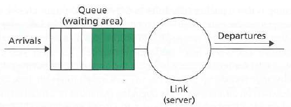
1.5.10 Queuing
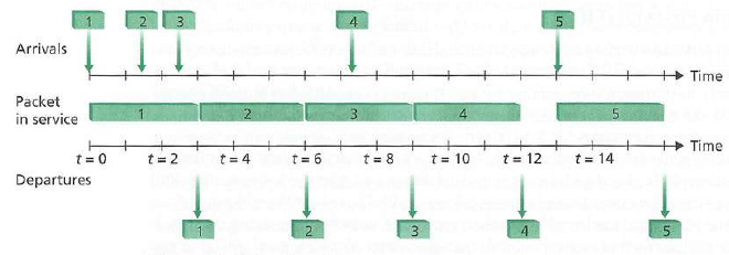
1.5.10.0.1 FIFO
first-in-first out
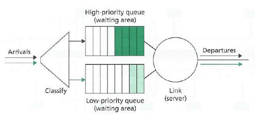
1.5.10.0.2 Priority queue
Who determines priority?
1.5.10.0.3 Round-robin and weighted
fair queuing
1.6 Architecture
Network layer components
1.6.1 IP addresses in routers
The boundary between the host and the physical link is called an
interface.
The boundary between the router and any one of its links is also
called an interface.
A router thus has multiple interfaces, one for each of its
links.
Every host and router is capable of sending and receiving IP
datagrams, and thus IP requires each host and router interface
to have its own IP address.
An IP address is technically associated with an
interface, rather than with the host or router containing that
interface.
Show some virtual interfaces.
What does Wireshark do with these?
I tried to come up with an IPv4 joke,
but the good ones were all already exhausted.
1.7.1 IPv4 address
04-NetworkData/IPv4_address.png
1.7.2 Examples
1.2.3.4 corresponds to 00000001 00000010 00000011 00000100
127.0.0.1 corresponds to 01111111 00000000 00000000 00000001
255.255.255.255 corresponds to 11111111 11111111 11111111 11111111
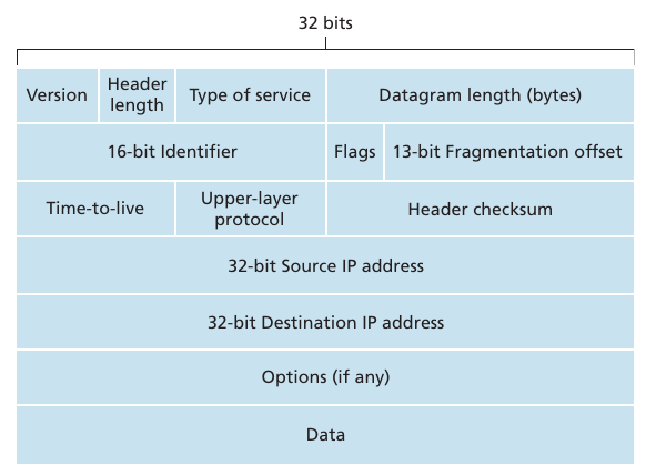
1.7.3 IPv4 Datagram header
04-NetworkData/kurose_ch4_12.png
Version number
4 bits specify the IP protocol version of the datagram.
Router can determine how to interpret the remainder of the IP
datagram.
Different versions of IP use different datagram formats.
Header length
Because an IPv4 datagram can contain a variable number of options
(which are included in the IPv4 datagram header), these 4 bits are
needed to determine where in the IP datagram the data actually
begins.
Most IP datagrams do not contain options, so the typical IP datagram
has a 20-byte header.
Type of service
included in the IPv4 header to allow different types of IP datagrams
(for example, datagrams particularly requiring low delay, high
throughput, or reliability) to be distinguished from each other.
For example, it might be useful to distinguish real-time datagrams
(such as those used by an IP telephony application) from non-real-time
traffic (for example, FTP).
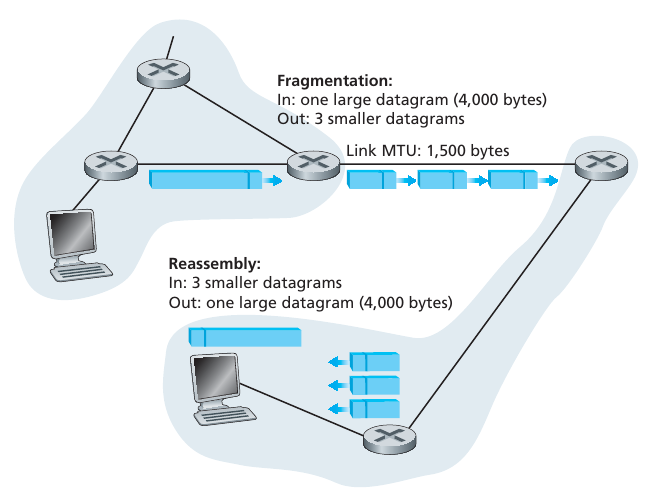
Datagram length
total length of the IP datagram (header plus data), measured in
bytes.
Datagrams are rarely larger than 1,500 bytes.
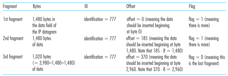
Identifier, flags, fragmentation offset
These three fields have to do with so-called IP fragmentation.
Time-to-live
included to ensure that datagrams do not circulate forever (due to,
for example, a long-lived routing loop)
Decremented by one each time the datagram is processed by a
router.
If the TTL field reaches 0, the datagram must be dropped.
Protocol
Intended to be used only when an IP datagram reaches its final
destination.
Value of this field indicates the specific transport-layer protocol
to which the data portion of this IP datagram should be passed.
For example, a value of 6 indicates that the data portion is passed
to TCP, while a value of 17 indicates that the data is passed to
UDP.
Header checksum
aids a router in detecting bit errors in a received IP
datagram.
Source and destination IP addresses
When a source creates a datagram, it inserts its IP address into the
source IP address field and inserts the address of the ultimate
destination into the destination IP address field.
Often the source host determines the destination address via a DNS
lookup.
Options
allow an IP header to be extended.
Header options were meant to be used rarely.
Data (payload)
In most circumstances, the data field of the IP datagram contains
the transport-layer segment to be delivered to the destination.
Total of 20 bytes of header (assuming no options).
If the datagram carries a TCP segment, then each (nonfragmented)
datagram carries a total of 40 bytes of header (20 bytes of IP header
plus 20 bytes of TCP header) along with message.
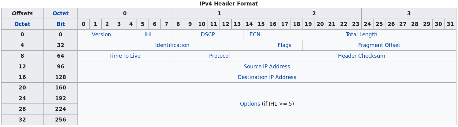
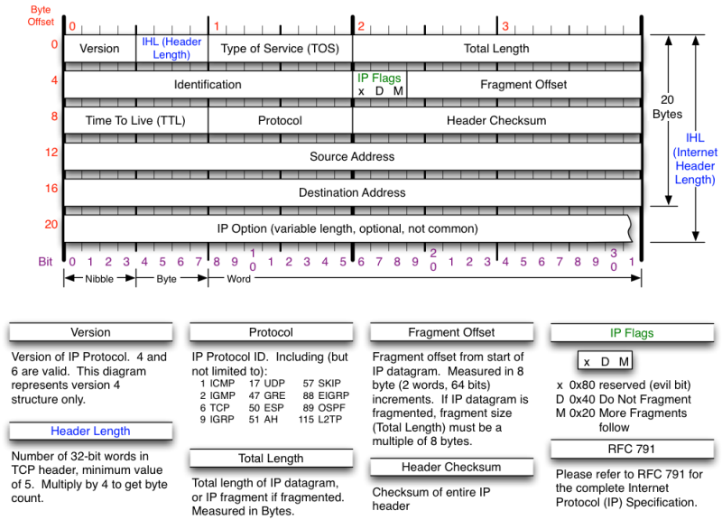
IPv4 Datagram header details
Version
The first header field in an IP packet is the four-bit version
field.
Internet Header Length (IHL)
The Internet Header Length (IHL) field has 4 bits, which is the
number of 32-bit words.
Since an IPv4 header may contain a variable number of options, this
field specifies the size of the header (this also coincides with the
offset to the data).
Differentiated Services Code Point (DSCP)
Originally defined as the Type of service (ToS) field.
An example is Voice over IP (VoIP), which is used for interactive
data voice exchange.
Explicit Congestion Notification (ECN)
This field is defined in RFC 3168 and allows end-to-end notification
of network congestion without dropping packets.
ECN is an optional feature that is only used when both endpoints
support it and are willing to use it.
It is only effective when supported by the underlying network.
Total Length
This 16-bit field defines the entire packet size in bytes, including
header and data.
The minimum size is 20 bytes (header without data) and the maximum
is 65,535 bytes.
All hosts are required to be able to reassemble datagrams of size up
to 576 bytes, but most modern hosts handle much larger packets.
Sometimes links impose further restrictions on the packet size, in
which case datagrams must be fragmented.
Fragmentation in IPv4 is handled in either the host or in
routers.
Identification
This field is an identification field and is primarily used for
uniquely identifying the group of fragments of a single IP
datagram.
Flags
A three-bit field follows and is used to control or identify
fragments.
Fragment Offset
The fragment offset field is measured in units of eight-byte
blocks.
It is 13 bits long and specifies the offset of a particular fragment
relative to the beginning of the original un-fragmented IP
datagram.
Time To Live (TTL)
An eight-bit time to live field helps prevent datagrams from
persisting (e.g. going in circles) on an internet.
It is specified in seconds, but time intervals less than 1 second
are rounded up to 1.
In practice, the field has become a hop count when the datagram
arrives at a router, the router decrements the TTL field by one.
When the TTL field hits zero, the router discards the packet and
typically sends an ICMP Time Exceeded message to the sender.
The program traceroute uses these ICMP Time Exceeded
messages to print the routers used by packets to go from the source to
the destination.
Protocol
This field defines the protocol used in the data portion of the IP
datagram, e.g., TCP, UDP, etc.
Header Checksum
The 16-bit checksum field is used for error-checking of the
header.
When a packet arrives at a router, the router calculates the
checksum of the header and compares it to the checksum field.
If the values do not match, the router discards the packet.
Errors in the data field must be handled by the encapsulated
protocol.
Source address
This field is the IPv4 address of the sender of the packet. Note
that this address may be changed in transit by a network address
translation device.
Destination address
This field is the IPv4 address of the receiver of the packet. As
with the source address, this may be changed in transit by a network
address translation device.
Options
The options field is not often used.
Data
The data portion of the packet is not included in the packet
checksum.
Its contents are interpreted based on the value of the Protocol
header field.
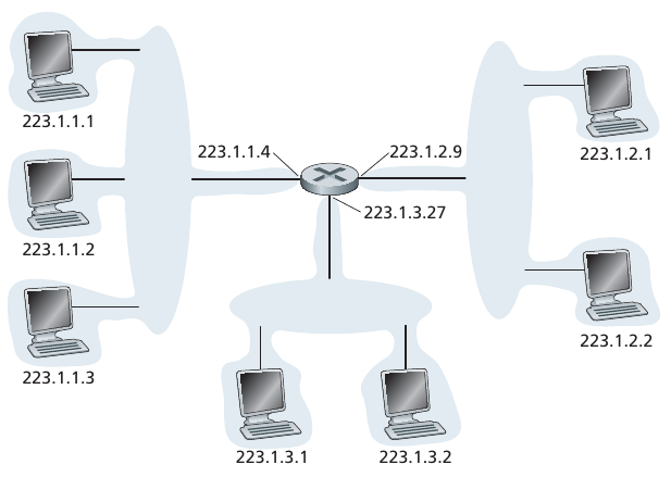
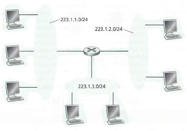
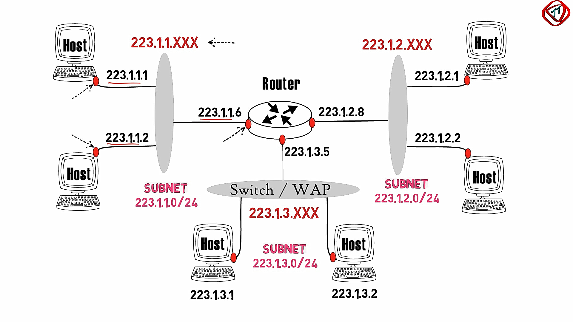
Three separate sub-networks (sub-nets) each has it’s own block of IP
addresses:
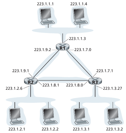
Put more routers in the middle, and it’s like the internet:
1.8.1 Sub-net addressing
Hierarchically divide IP addresses and networks:
To determine the sub-nets, detach each interface from its host or
router,
creating islands of isolated networks,
with interfaces terminating the end points of the isolated
networks.
Each of these isolated networks is called a sub-net.
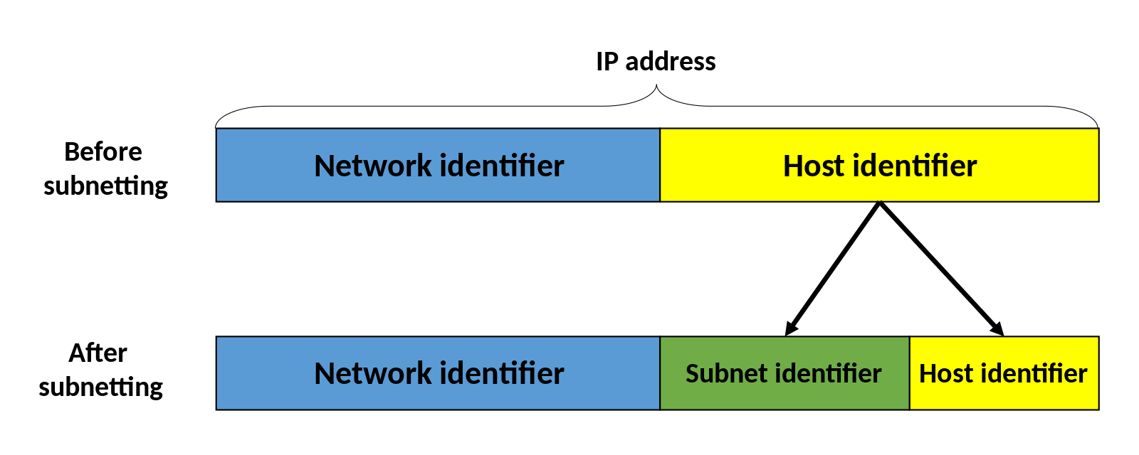
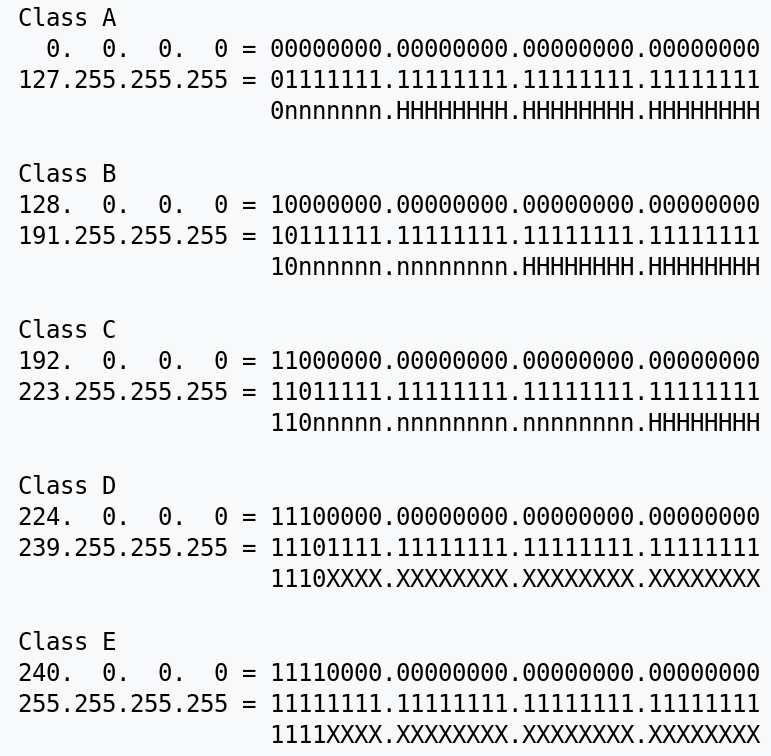
The old way of hierarchically dividing up IP addresses: https://en.wikipedia.org/wiki/Classful_network
where the IP address is divided up into:
n is the network portion
H is the host portion
Above, the general pattern is illustrated with the n and H, but the
particular ranges of IP addresses are those arbitrarily actually
assigned to the world by ICANN.
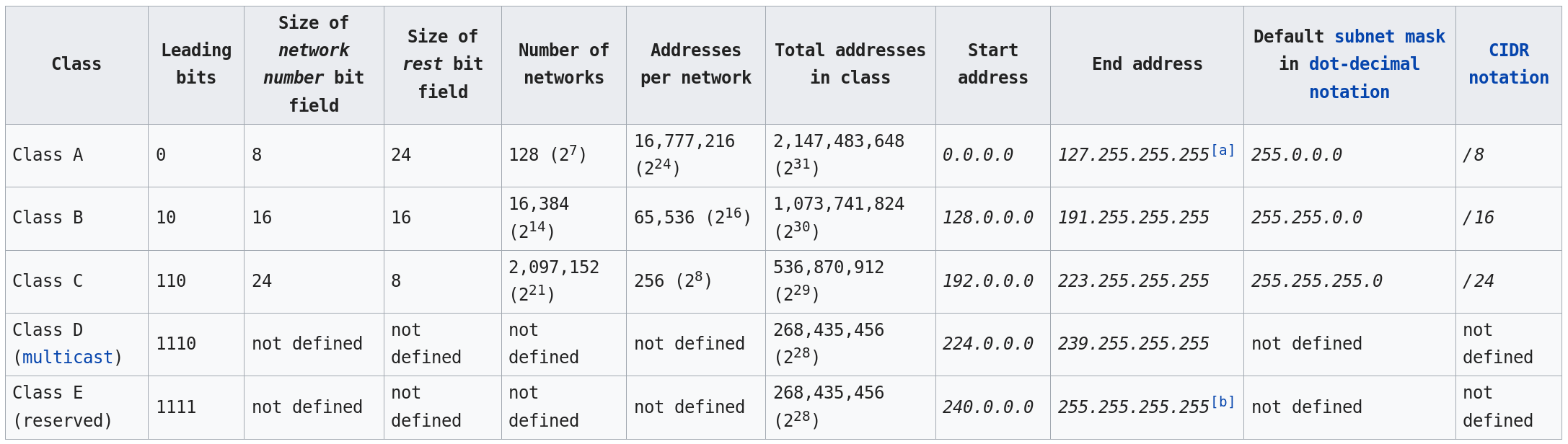
Above, this table not only illustrates the general pattern, but also the
specific more arbitrary ranges assigned to the world by ICANN.
Columns that are general:
Leading bits
Size of network number bit field
Size of rest bit field
Addresses per network
Default sub-net mask
CIDR notation
Columns that are particular to the actual arbitrary real
assignment
Number of networks
Total addresses in class
Start address
End address
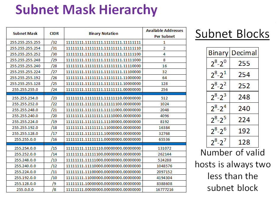
1.8.1.2 CIDR
The routing prefix may be written as the first address of a network,
followed by a slash character (/), and ending with the bit-length of the
prefix.
For example, 198.51.100.0/24 is the prefix of the Internet Protocol
version 4 network starting at the given address, having 24 bits
allocated for the network prefix, and the remaining 8
bits reserved for host addressing.
Variable-length sub-net masking (VLSM) technique,
which allows the specification of arbitrary-length prefixes.
CIDR introduced a new method of representation for IP addresses, now
commonly known as CIDR notation, in which an address or routing prefix
is written with a suffix indicating the number of bits of the prefix,
such as 192.0.2.0/24
sub-net portion of address of arbitrary length
address format: a.b.c.d/x, where x is # bits in sub-net portion of
address
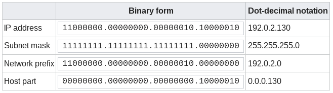
You may have understood this in integer encoding:
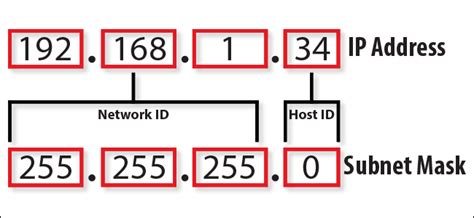
Sub-net masks are often expressed in dot-decimal notation like an
address.
For example, 255.255.255.0 is the sub-net mask for the prefix
198.51.100.0/24.
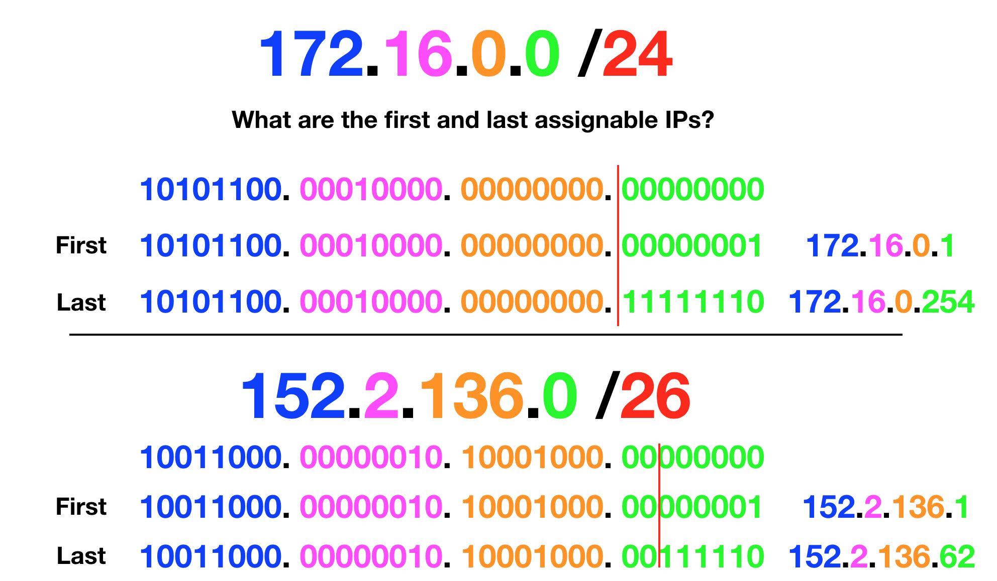
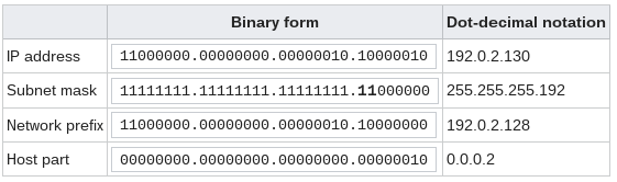
But, sub-net masks really make sense when you think about IP
addresses in binary encoding:
For IPv4, a network may also be characterized by its sub-net mask or
netmask.
This is a binary trick, to illustrate the h.N pattern.
Functionally, it ends up cleaving the IP address into two parts, the
leading network portion, and the trailing host portion.
Specifically, it is a bitmask applied by a bitwise
AND operation,
to any IP address in the network, yielding the routing prefix (see
below).
IPv4 network standards reserve the entire address block 127.0.0.0/8
(more than 16 million addresses) for loopback purposes…
That means any packet sent to any of those addresses is looped
back.
The address 127.0.0.1 is the standard address for IPv4
loopback traffic.
The rest are not supported by all operating systems.
However they can be used to set up multiple server applications on
the host, all listening on the same port number.
The IPv6 standard assigns only a single address for loopback,
::1
The resolution of the name localhost to one or more IP addresses is
normally configured by the following lines in the operating system’s
hosts file /etc/hosts (view mine):
vim /etc/hosts 127.0.0.1 localhost ::1 localhost
Last row above is IPv6 shorthand (more below).
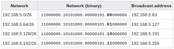
1.8.1.4.2 Broadcast and addresses
ending in 0 or 255
255.255.255.255 is used for broadcast transmission to
all hosts on a link.
IPv4 uses this all-ones (in binary) host address
It is the last address within a network.
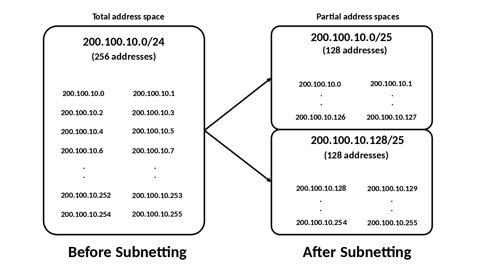
The number of sub-networks available, and the number of possible
hosts in a network may be readily calculated.
In the example (below) two bits were borrowed to create
sub-networks, thus creating 4 (22) possible sub-nets.
1.8.1.4.3 Private addresses
192.168.0.1 jokes are best told in private…
24-bit block 10.0.0.0/8 10.0.0.0 10.255.255.255 16777216 Single
Class A.
20-bit block 172.16.0.0/12 172.16.0.0 172.31.255.255 1048576
Contiguous range of 16 Class B blocks.
16-bit block 192.168.0.0/16 192.168.0.0 192.168.255.255 65536
Contiguous range of 256 Class C blocks.
You can do whatever you want with these on your private network,
e.g., at home.
1.8.1.4.4 Link-local addresses
RFC 3927 defines the special address block
169.254.0.0/16 for link-local addressing.
These addresses are only valid on the link (such as a local network
segment or point-to-point connection) directly connected to a host that
uses them.
These addresses are not routable.
Like private addresses, these addresses cannot be the source or
destination of packets traversing the internet.
These addresses are primarily used for address auto-configuration
(Zeroconf) when a host cannot obtain an IP address from a DHCP server or
other internal configuration methods.
+++++++++++++++++++ Cahoot-04-8
1.9 Obtaining IP addresses
An IPv4 address walks into a bar and yells,
“Bartender! Give me a cidr, I’m exhausted!”
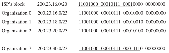
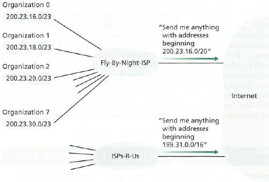
ISPs provides addresses from a larger block of addresses that had
already been allocated to that ISP.
For example, the ISP may itself have been allocated the address
block 200.23.16.0/20.
The ISP, in turn, could divide its address block into eight
equal-sized contiguous address blocks, and give one of these address
blocks out to each of up to eight organizations that are supported by
this ISP, as shown below.
(underlined the sub-net part of these addresses for your
convenience.)
There are eight /23 sub-nets in one /20 sub-net (3 bits consumed,
2**3=8)
1.9.1 Allocation
https://en.wikipedia.org/wiki/ICANN
The IP address space is managed globally by the Internet Assigned
Numbers Authority (IANA),
and by five regional Internet registries (RIR) responsible in their
designated territories,
for assignment to end users and local Internet registries, such as
Internet service providers.
ICANN assigns blocks to ISPs, regions, countries, etc.
Companies (including ISPs) buy and sell them.
ISPs assign them to consumers or other businesses.
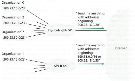
1.9.1.1 Hierarchy in practice
After a company re-selling a block:
Ask: What happens when the ranges are not nicely divided?
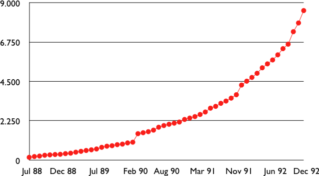
The consequence of the above, with longest-prefix matching is:
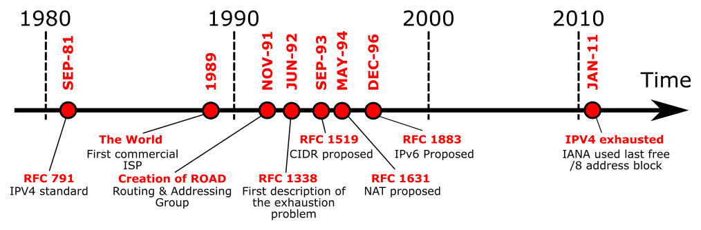
Evolution of the size of the routing tables on the Internet (Jul
1988- Dec 1992 - source : RFC 1518)
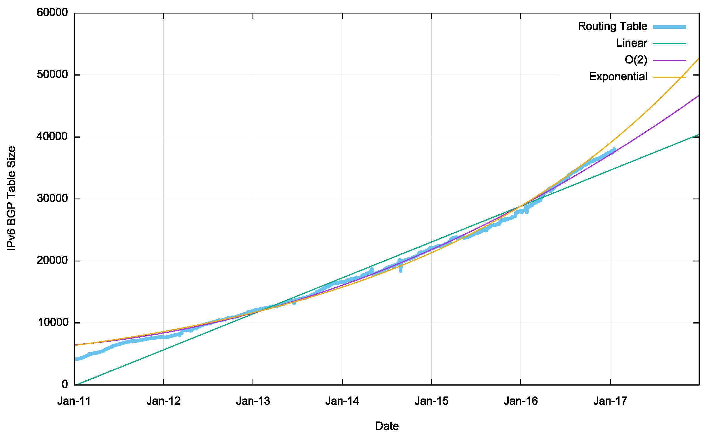
and more modern:
1.9.1.2.1 Solutions
Some mitigation efforts and technologies include:
use of network address translation (NAT)[18] which allows a private
network to use one public IP address and permitting private addresses in
the private network;
use of private network addressing;[19]
name-based virtual hosting of web sites;
tighter control by regional Internet registries on the allocation of
addresses to local Internet registries;
network renumbering and subnetting to reclaim large blocks of
address space allocated in the early days of the Internet, when the
Internet used inefficient classful network addressing.
Client-server
When logging into a network, how does an interface get an IP
address?
Either:
1. Hard coded by sys-admin
2. DHCP
Goal: Allow host to dynamically obtain its IP address
from network server when it joins network.
Host can also renew its lease on an address in use.
Allows reuse of retired addresses (only hold address while
connected/“on”).
DHCP is a client-server protocol:
Host broadcasts “DHCP discover” msg [optional]
DHCP server responds with “DHCP offer” msg [optional]
Host requests IP address: “DHCP request” msg
DHCP server sends address: “DHCP ack” msg
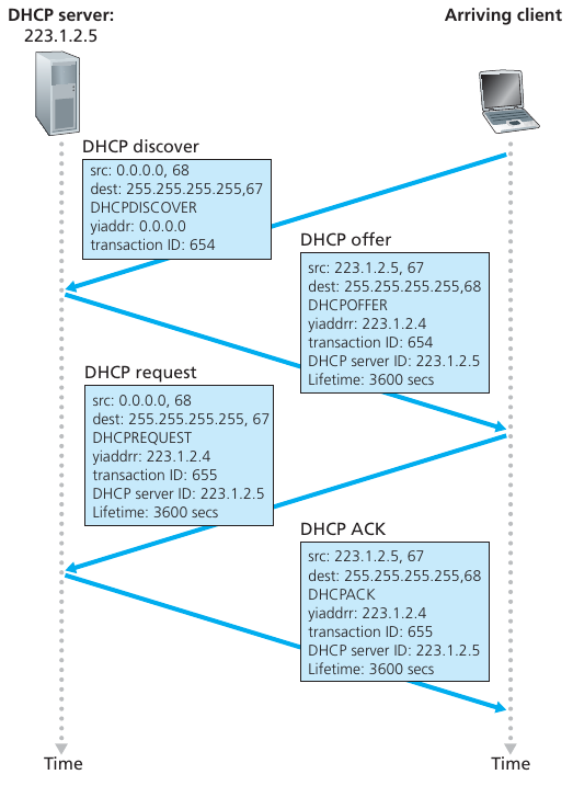
1.9.2.1 DHCP process
DHCP discover message, which a client sends within
a UDP packet to port 67, broadcast
A DHCP server receiving a DHCP discover message responds to the
client with a DHCP offer message that is broadcast to
all nodes on the sub-net, again using the IP broadcast address of
255.255.255.255.
DHCP request. The newly arriving client will choose
from among one or more server offers and respond to its selected offer
with a DHCP request message, echoing back the configuration
parameters.
DHCP ACK. The server responds to the DHCP request
message with a DHCP ACK message, confirming the requested
parameters.
DHCP query response
In addition to host IP address assignment,
DHCP also allows a host to learn additional information, such as
its:
subnet mask (indicating network versus host portion of address),
the address of its first-hop router (often called the default gateway),
and
the address of its local DNS server.
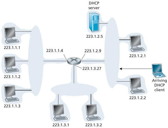
1.9.2.2 Example
Connecting laptop needs its IP address, addr of first-hop router,
addr of DNS server: use DHCP
DHCP request encapsulated in UDP, encapsulated in IP, encapsulated
in 802.1 Ethernet
Ethernet frame broadcast (dest: FFFFFFFFFFFF) on LAN, received at
router running DHCP server
Ethernet demuxed to IP demuxed, UDP demuxed to DHCP
DCP server formulates DHCP ACK containing client’s IP address, IP
address of first-hop router for client, name and IP address of DNS
server
encapsulation of DHCP server, frame forwarded to client, demuxing up
to DHCP at client
client now knows its IP address, name and IP address of DSN server,
IP address of its first-hop router
DHCP provides an IP address, and also usually more, including:
IP address
Subnet Mask
IP address of a Default Gateway (router)
IP address of a DNS server
1.10 MiddleBoxes
https://en.wikipedia.org/wiki/Middlebox#Criticism_and_challenges
“Middleboxes have generated technical challenges for application
development and have incurred scorn and dismay in the network
architecture community for violating the end-to-end principle of
computer system design.”
Some types of middlebox covered here:
Firewall, IPS, IDS
NAT
Remote generalized SDN / Deep Packet Inspectors (DPI)
Load balancers
1.10.1 (1) Firewall, IPS, IDS
The first middlebox is:
1.10.1.0.1 Firewall (more
later)
The first firewalls included configurable packet filters.
A packet filter is a set of rules defining the security policy of a
network.
In practice, these rules are based on the values of fields in the IP
or transport layer headers.
Any field of the IP or transport header can be used in a firewall
rule, but the most common ones are:
filter on the source address. For example, a company may decide to
discard all packets received from one of its competitors. In this case,
all packets whose source address belong to the competitor’s address
block would be rejected
filter on destination address. For example, the hosts of the
research lab of a company may receive packets from the global Internet,
but not the hosts of the financial department
filter on the Protocol number found in the IP header. For example, a
company may only allow its hosts to use TCP or UDP, but not other, more
experimental, transport protocols
filter on the TCP or UDP port numbers. For example, only the DNS
server of a company should received UDP segments whose destination port
is set to 53 or only the official SMTP servers of the company can send
TCP segments whose source ports are set to 25
filter on the TCP flags. For example, a simple solution to prohibit
external hosts from opening TCP connections with hosts inside the
company is to discard all TCP segments received from the external
interface with only the SYN flag set.
Such firewalls are often called stateless firewalls because they do
not maintain any state about the TCP connections that pass through
them.
Another type of firewalls are stateful firewalls.
A stateful firewall tracks the state of each TCP connection passing
through it and maintains a TCB for each of these TCP connection.
This TCB allows it to reassemble the received segments in order to
extract their payload and perform verifications in the application
layer.
Some firewalls are able to inspect the URLs accessed using HTTP and
log all URLs visited or block TCP connections where a dangerous URL is
exchanged.
Some firewalls can verify that SMTP commands are used when a TCP
connection is established on port 25 or that a TCP connection on port 80
carries HTTP commands and responses.
1.10.1.0.2 IDS
Intrusion detection system
Additional protection can be provided with an IDS.
An IDS, typically situated at the network boundary, performs “deep
packet inspection,” examining not only header fields but also the
payloads in the datagram (including application-layer data).
An IDS has a database of packet signatures that are known to be part
of attacks.
This database is automatically updated as new attacks are
discovered.
As packets pass through the IDS, the IDS attempts to match header
fields and payloads to the signatures in its signature data-base.
If such a match is found, an alert is created.
1.10.1.0.3 IPS
An intrusion prevention system (IPS) is similar to
an IDS, except that it actually blocks packets in addition to creating
alerts.
Network Address Translation (NAT) was proposed in [TE1993] and RFC
3022 as a short term solution to deal with the expected shortage of IPv4
addresses in the late 1980s - early 1990s.
1.10.2.1 Motivation
Local network uses just one IP address as far as outside world is
concerned:
range of addresses not needed from ISP: just one IP address for all
devices
can change addresses of devices in local network without notifying
outside world
can change ISP without changing addresses of devices in local
network
devices inside local net not explicitly addressable, visible by
outside world (a security plus)
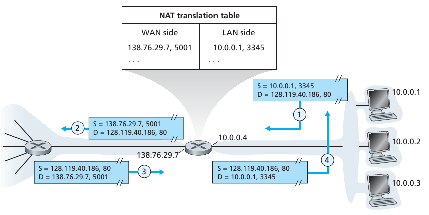
1.10.2.2 Process
NAT router must:
Outgoing datagrams: replace (source IP address,
port #) of every outgoing datagram to (NAT IP address, new port #)
. . . remote clients/servers will respond using (NAT IP address, new
port #) as destination addr
remember (in NAT translation table) every (source
IP address, port #) to (NAT IP address, new port #) translation
pair
incoming datagrams: replace (NAT IP address, new
port #) in dest fields of every incoming datagram with corresponding
(source IP address, port #) stored in NAT table
1.10.2.3 Details
NAT router behaves to the outside world as a single device with a
single IP address, matching external ports to internal network IP/port
combinations
10.0.0/8 is reserved by RFC as private network or real with private
address
What are problems with NAT?
What are middleboxes? (this is usually a derogatory
term)
Network-layer devices that overstep their bounds: NAT, load
balancing of traffic flow, firewalling, etc.,
Wait, isn’t this just SDN, overzealous middleboxes??
1.10.2.4 Summary
16-bit port-number field:
60,000 simultaneous connections with a single LAN-side address!
NAT is controversial:
routers should only process up to layer 3
address shortage should be solved by IPv6
violates end-to-end argument
NAT possibility must be taken into account by app designers, e.g.,
P2P applications
NAT traversal
what if client wants to connect to server behind NAT?
1.10.2.4.1 Wireshark NAT
1.10.3 (3) Generalized forwarding
and software defined networking (SDN)
Packets can be routed based on arbitrary header content (think
firewalls above).
SDN can route packets based on application, data-link, transport, or any
layer data,
for managing traffic, security, payment, or whatever else desired.
I heard this really great IPv6 joke,
but I just don’t think you’re ready for it.
IPv6 streamlined the protocol, eliminating work for core routers,
deferring that work to the periphery.
For example, IPv6 does not calculate checksums or fragmentation.
This supports the: https://en.wikipedia.org/wiki/End-to-end_principle
1.11.1 IPv6 address format
04-NetworkData/IPv6_address.png
The sad thing about IPv6 jokes,
is that almost no one understands them,
and no one is using them yet.
Examples 2001:db8:0:0:8:800:200c:417a is represented as
2001:db8::8:800:200c:417a ff01:0:0:0:0:0:0:101 is represented as
ff01::101 0:0:0:0:0:0:0:1 is represented as ::1 0:0:0:0:0:0:0:0 is represented as ::
1.11.1.1 But the “:” is used for
port number!
Colon (:) characters in IPv6 addresses may conflict with the
established syntax of resource identifiers, such as URIs and URLs.
The colon is conventionally used to terminate the host path before a
port number.
To alleviate this conflict, literal IPv6 addresses are enclosed in
square brackets in such resource identifiers.
For example, an IPv6 address typed into your web browser: http://[2001:db8:85a3:8d3:1319:8a2e:370:7348]/
When the URL also contains a port number the notation is: https://[2001:db8:85a3:8d3:1319:8a2e:370:7348]:443/
where the trailing 443 is the example’s port number.
IPv6 increases the potential size of the IP address range from
32 to 128 bits.
This ensures that the world won’t run out of IP addresses.
Now, every grain of sand, toaster, and television on the planet can
be IP-addressable!
1.11.2.1.2Addressing
methods (scope of address)
Unicast:
address identifies a single network interface.
The Internet Protocol delivers packets sent to a unicast address to
that specific interface.
Unicast also exists in IPv4
Multicast:
address is also used by multiple hosts that acquire the multicast
address destination by participating in the multicast distribution
protocol among the network routers.
A packet that is sent to a multicast address is delivered to all
interfaces that have joined the corresponding multicast group.
IPv6 does not implement broadcast addressing.
Broadcast’s traditional role is subsumed by multicast addressing to
the all-nodes link-local multicast group ff02::1.
However, the use of the all-nodes group is not recommended, and most
IPv6 protocols use a dedicated link-local multicast group to avoid
disturbing every interface in the network.
Multicast also exists in IPv4
Anycast
IPv6 introduced a new type of address, called an
anycast address, which allows a datagram to be
delivered to any one of a group of hosts.
This feature could be used, for example, to send an HTTP GET to the
nearest of a number of mirror sites that contain a given document.
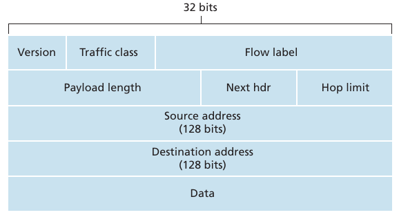
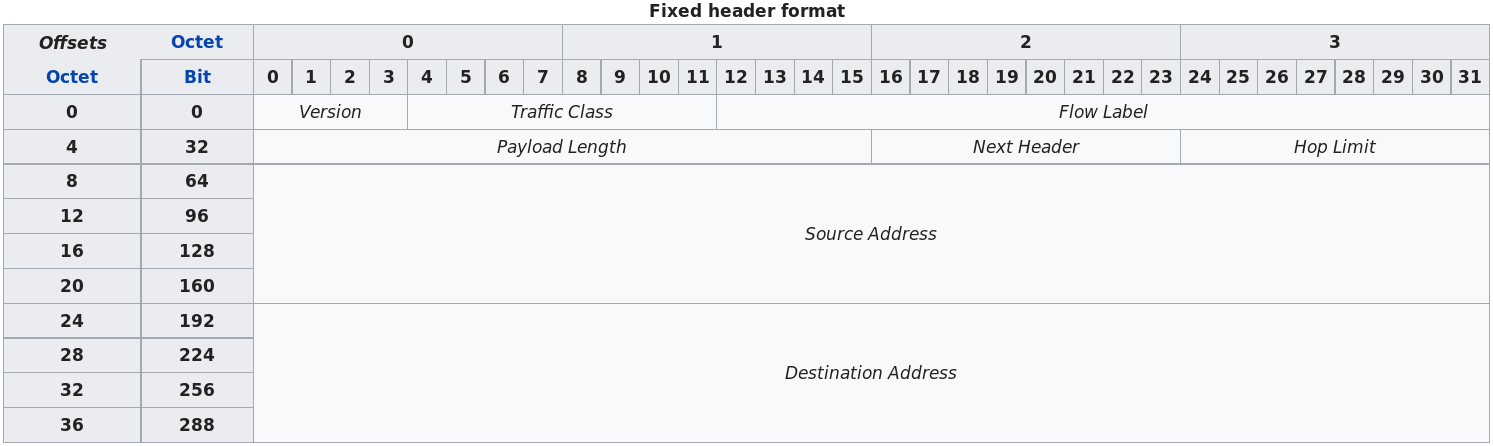
1.11.2.2A streamlined
40-byte header:
A number of IPv4 fields have been dropped or made optional.
The resulting 40-byte fixed-length header allows for faster
processing of the IP datagram.
A new encoding of options allows for more flexible options
processing.
1.11.2.3Flow labeling and
priority:
IPv6 has an elusive definition of a flow.
RFC 1752 and RFC 2460 state that this allows “labeling of packets
belonging to particular flows for which the sender requests special
handling, such as a non-default quality of service or real-time
service.”
For example, audio and video transmission might likely be treated as
a “flow”.
On the other hand, the more traditional applications, such as file
transfer and e-mail, might not be treated as flows.
It is possible that the field could indicate traffic carried by a
high-priority user.
For example, someone paying for better service for their traffic,
might also be treated as a flow.
The following fields are defined in IPv6:
Version
This 4-bit field identifies the IP version number.
Not surprisingly, IPv6 carries a value of 6 in this field.
Note that putting a 4 in this field does not create a valid IPv4
datagram.
If it did, life would be a lot simpler… see the discussion below
regarding the transition from IPv4 to IPv6. Traffic class
This 8-bit field is similar to the TOS field we saw in IPv4.
Flow label
As discussed above, this 20-bit field is used to identify a flow of
datagrams.
Payload length
This 16-bit value is treated as an unsigned integer
It is the number of bytes in the IPv6 datagram, following the
fixed-length, 40-byte datagram header.
Next header
This field identifies the protocol to which the contents (data
field) of this datagram will be delivered (for example, to TCP or
UDP).
The field uses the same values as the protocol field in the IPv4
header.
This field usually specifies the transport layer protocol used by a
packet’s payload.
When extension headers are present in the packet this field
indicates which extension header follows.
The values are shared with those used for the IPv4 protocol field,
as both fields have the same function (see List of IP protocol
numbers)
The next header enables a neat extensibility:
extra headers, like IPsec, or others, can be layered between IP and
the Transport layer above (UDP/TCP):
The contents of this field are decremented by one by each router
that forwards the datagram.
If the hop limit count reaches zero, the datagram is discarded.
This is better named than the IPv4 TTL field, which was really
hop-limit anyway.
Source and destination addresses
The various formats of the IPv6 128-bit address are described in RFC
4291.
Data
This is the payload portion of the IPv6 datagram.
When the datagram reaches its destination, the payload will be
removed from the IP datagram and passed on to the protocol specified in
the next header field.
IPv6 Datagram header details
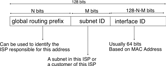
1.11.3 IPv6 sub-net addressing
Structure of IPv6 unicast addresses:
An IPv6 unicast address is composed of three chunks:
1. A global routing prefix that is assigned to the Internet Service
Provider that owns this block of addresses
2. A subnet identifier that identifies a customer of the ISP
3. An interface identifier that identifies a particular interface on an
endsystem
Interface identifiers are always 64 bits wide.
This implies that, while there are 2128 different IPv6
addresses, they must be grouped in 264 subnets.
This could appear as a waste of resources
However, using 64 bits for the host identifier allows IPv6 addresses
to be auto-configured, and also provides some benefits from a security
point of view, as explained in section ICMPv6.
Given an address size of 128 bits, an IPv6 address therefore usually
has a /64 routing prefix
128 - 64 = 64 most significant bits
The standard sub-nets are /64
Example of dividing up subnets:
Each “site” would have 216 subnets, where each subnet is
264 large.
1.11.4 Obtaining an address
1.11.4.1 Allocation?
Same as with IPv4 above: super-governmental agencies and companies
assign them, and they are re-sold.
On OS-network system startup, a node automatically creates a
link-local address on each IPv6-enabled interface, even if globally
routable addresses are manually configured or obtained via other
configuration protocols.
In IPv4, typical “configuration protocols” include DHCP or PPP.
For IPv6, DHCPv6 exists, but IPv6 hosts normally use the
Neighbor Discovery Protocol (NDP) to create a globally
routable unicast address.
The host sends router solicitation requests, and an IPv6 router
responds with a prefix assignment
NDP defines five ICMPv6 packet types for the purpose of
router solicitation,
router advertisement,
neighbor solicitation,
neighbor advertisement, and
network redirects (like ARP next layer down).
1.11.4.2.3 Modified EUI-64
addresses
For a globally routeable anycast address, as mentioned earlier, most
IPv6 addresses can be divided into a 64-bit network prefix and a 64-bit
“host” portion, the latter corresponding to the “host” bits of an IPv4
address.
These host-portion bits are known officially as the interface
identifier
The interface portion was originally derive from your MAC address.
EUI-64 interface identifiers turned out to introduce a major privacy
concern, Why?
No matter where a (portable) host connects to the Internet, home,
work, airport, or Internet cafe, such an interface identifier always
remains the same, and thus serves as a permanent host fingerprint!
That is clearly bad news for internet freedom,
As a result, EUI-64 identifiers are now discouraged for personal
workstations and mobile devices.
We assign each interface in IPv6 multiple IP addresses:
That is, each interface is multi-homed.
1.11.5.0.1 Scope
https://en.wikipedia.org/wiki/IPv6_address#Address_scopes
Each IPv6 address has a scope, which specifies in which part of the
network it is valid and unique.
Some addresses are assumed to be unique, and are only routeable on the
local (sub-)network.
Others must be globally unique, and are globally routeable.
IPv6 addresses are classified by three types of networking
methodologies:
1. unicast addresses identify each network
interface,
2. anycast addresses identify a group of interfaces,
usually at different locations of which the nearest one is automatically
selected, and
3. multicast addresses are used to deliver one packet
to many interfaces (e.g., only need to hit one of google’s servers)
The typical size of the IPv6 anycast address blocks give out
are:
/32 for an Internet Service Provider
/48 for a single company
/56 for small user sites (organizations)
/64 for a single user (e.g. a home user connected via ADSL)
/128 in the rare case when it is known that no more than one end-host
will be attached
1.11.5.0.3 Link-local (type of
unicast)
Routers won’t route these globally.
All interfaces of IPv6 hosts require a link-local address.
IPv6 link-local address were traditionally derived from the MAC
address of the underlying network interface card and the prefix
fe80::/10
However, this scheme has been replaced by RFC 8064 with a hash-based
scheme specified in RFC 7217.
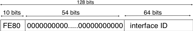
IPv6 defines link-local addresses, with so-called link-local scope,
intended to be used only on a single LAN and never routed.
These begin with the 64-bit link-local prefix consisting of the ten
bits 1111 1110 10 followed by 54 more zero bits; that is,
fe80::/64.
The remaining 64 bits are the interface identifier for the link
interface in question, above.
The EUI-64 link-local address of a machine with Ethernet address
00:a0:cc:24:b0:e4 is thus
fe80::2a0:ccff:fe24:b0e4.
The main applications of link-local addresses are as a “bootstrap”
address for global-address auto-configuration.
Link-local they may use your MAC, but that’s not a concern here,
because they’re only for local routing.
Have global scope, but they are not globally administered.
As a result, only other hosts in the same administrative domain
(e.g., an organization), or within a cooperating administrative domain
are able to reach such addresses, if properly routed.
As their scope is global, these addresses are valid as a source
address when communicating with any other global-scope address, even
though it may be impossible to route packets from the destination back
to the source.
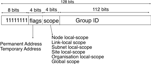
1.11.5.0.6 Multicast
IPv6 has moved away from LAN-layer broadcast, instead providing a
wide range of LAN-layer multicast groups.
The low order 112 bits of an IPv6 multicast address are the group’s
identifier.
The high order bits are used as a marker to distinguish multicast
addresses from unicast addresses.
Notably, the 4 bits flag field indicates whether the address is
temporary or permanent.
Finally, the scope field indicates the boundaries of the forwarding of
packets destined to a particular address.
A link-local scope indicates that a router should not forward a packet
destined to such a multicast address.
An organization local-scope indicates that a packet sent to such a
multicast destination address should not leave the organization.
Finally the global scope is intended for multicast groups spanning the
global Internet.
1.11.5.0.7 Anycast
IPv6 also introduced anycast addresses.
An anycast address might be assigned to each of a set of routers (in
addition to each router’s own unicast addresses);
a packet addressed to this anycast address would be delivered to
only one member of this set.
Note that this is quite different from multicast addresses;
a packet addressed to the latter is delivered to every member of the
set.
++++++++++++++++++ Cahoot-04-11
1.11.6 Adoption / deployment
https://en.wikipedia.org/wiki/IPv6_deployment
IPv6 was designed as a replacement for IPv4 which has been in use since
1982, and is in the final stages of exhausting its unallocated address
space, but still carries most Internet traffic.
By 2011, all major operating systems in use on personal computers and
server systems had production-quality IPv6 implementations.
Number of IPv6 prefixes and AS on the Internet since 2003
Monthly IPv6 allocations per RIR.
The bad thing about IPv6 jokes is that nobody wants to tell
them first.
IPv4 and IPv6 are, functionally, rather similar.
However, the widespread use of NAT in the IPv4 world makes IPv4 in
practice appear rather different.
IPv4 and IPv6 can, of course, coexist side-by-side, as two parallel
and independent IP layers.
But, the demand for IPv4-to-IPv6 connectivity has led to multiple
solutions.
Further, what if two central routers that are unavoidable can only
do IPv4?
This section can be broken down into a several different
situations:
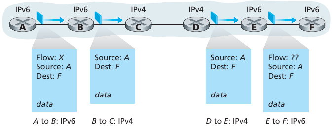
1. IPv6-only end-machine to IPv6-only end-machine connections, which
must pass through IPv4-only core.
2. IPv4-only end-machine to IPv4 end-machine connections, which must
pass through IPv6-only core (more rare in USA).
3. IPv6 and IPv4 co-existence, and prioritization when both are
available.
4. IPv6-only end-machine connecting to an IPv4-only end-machine, and
vice-versa.
For IPv4 addresses, DNS maintains so-called “A” records, for
“Address”.
The IPv6 equivalent is the “AAAA” record, for “Address four times
longer”.
A dual-stack machine usually requests both.
Whenever a DNS server delivers an IPv4 A record, it also includes
the corresponding AAAA record, much as IPv4 CNAME records are sent with
piggybacked corresponding A records.
Dual-stack
Machines that can do both IPv4 and IPv6
Probably the most straightforward way to introduce IPv6-capable
nodes is a dual-stack approach, where IPv6 nodes also have a complete
IPv4 implementation.
Such a node, referred to as an IPv6/IPv4 node in RFC 4213, has the
ability to send and receive both IPv4 and IPv6 datagrams.
When interoperating with an IPv4 node, an IPv6/IPv4 node can use
IPv4 datagrams
When interoperating with an IPv6 node, it can speak IPv6.
IPv6/IPv4 nodes must have both IPv6 and IPv4 addresses.
Nodes must be able to determine whether another node is IPv6-capable
or IPv4-only.
This problem can be solved using the DNS, which can return an IPv6
address if the node name being resolved is IPv6-capable, or otherwise
return an IPv4 address.
Of course, if the node issuing the DNS request is only IPv4-capable,
the DNS returns only an IPv4 address.
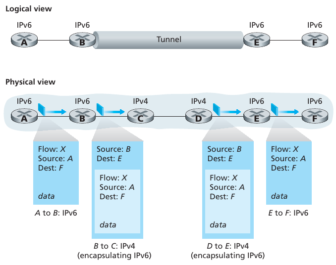
A tunnel broker provides IPv6 connectivity by encapsulating IPv6
traffic in IPv4 Internet transit links, typically using 6in4.
This establishes pseudo-end-to-end IPv6 tunnels within the IPv4
Internet.
While TLS or SSH secure application layer, IPsec can end-to-end
encrypt the network layer:
Cryptographic agreement.
Two communicating hosts to agree on cryptographic algorithms and
keys.
Encryption of IP datagram payloads.
When the sending host receives a segment from the transport layer, IPsec
encrypts the payload.
The payload can only be decrypted by IPsec in the receiving host.
Data integrity.
Allows the receiving host to verify that the datagram’s header fields
and encrypted payload were not modified,
while the datagram was en route from source to destination.
Origin authentication.
When a host receives an IPsec datagram from a trusted source (with a
trusted key see), the host is assured that the source IP address in the
datagram is the actual source of the datagram.
When two hosts have an IPsec session established between them, all TCP
and UDP segments sent between them will be encrypted and
authenticated.
IPsec therefore provides blanket coverage, securing all communication
between the two hosts for all network applications.
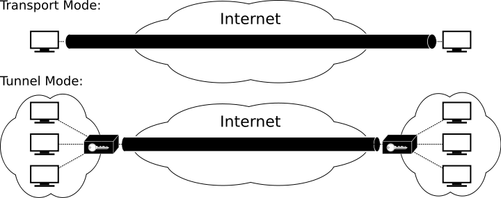
1.12.0.1 Modes
Two major modes of operation
1.12.0.1.1 Transport mode
In transport mode, only the payload of the IP packet is usually
encrypted or authenticated.
The routing is intact, since the IP header is neither modified nor
encrypted;
however, when the authentication header is used, the IP addresses
cannot be modified by network address translation, as this always
invalidates the hash value.
The transport and application layers are always secured by a hash,
so they cannot be modified in any way, for example by translating the
port numbers.
1.12.0.1.2 Tunnel mode
In tunnel mode, the entire IP packet is encrypted and
authenticated.
It is then encapsulated into a new IP packet with a new IP
header.
Tunnel mode is used to create virtual private networks for
network-to-network communications (e.g. between routers to link
sites),
host-to-network communications (e.g. remote user access) and
host-to-host communications (e.g. private chat).
Tunnel mode supports NAT traversal.
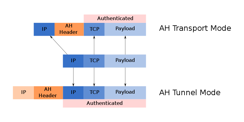
1.12.1 Functions
IPsec uses the following protocols to perform various functions:
Authentication Headers (AH)
Provides connectionless data integrity and data origin authentication
for IP datagrams and provides protection against replay attacks.
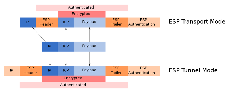
Encapsulating Security Payloads (ESP)
Provides confidentiality, connectionless data integrity, data origin
authentication, an anti-replay service (a form of partial sequence
integrity), and limited traffic-flow confidentiality.
Internet Security Association and Key Management Protocol
(ISAKMP)
Provides a framework for authentication and key exchange, with actual
authenticated keying material provided either by manual configuration
with pre-shared keys, Internet Key Exchange (IKE and IKEv2), Kerberized
Internet Negotiation of Keys (KINK), or IPSECKEY DNS records.
The purpose is to generate the Security Associations (SA) with the
bundle of algorithms and parameters necessary for AH and/or ESP
operations.
For more, see latter section (coming up).
1.13 Supporting and related
protocols
IP can operate over many data-link layer protocols, and other
protocols operate above it at the transport layer.
Some of this stuff is not quite data, not quite control… ICMP differs from transport protocols such as TCP and
UDP, in that:
it is not typically used to exchange data between systems,
nor is it regularly employed by end-user network applications,
with the exception of some diagnostic tools like ping and
traceroute.
ICMP uses the basic support of IP as if it were a higher level
protocol,
however, ICMP is actually an integral part of IP.
Although ICMP messages are contained within standard IP packets,
ICMP messages are usually processed as a special case,
distinguished from normal IP processing.
It is often necessary to inspect the contents of the ICMP message,
and deliver an appropriate error message,
to the application responsible for transmission of the IP packet,
that prompted the sending of the ICMP message.
ICMP is a network layer protocol.
There is no TCP or UDP port number associated with ICMP packets,
as these numbers are associated with the transport layer above.
ICMP is often considered part of IP,
but architecturally it lies just above IP,
as ICMP messages are carried inside IP datagrams.
That is, ICMP messages are carried as IP payload,
just as TCP or UDP segments are carried as IP payload.
When a host receives an IP datagram,
with ICMP specified as the upper-layer protocol,
it demultiplexes the datagram’s contents to ICMP,
just as it would demultiplex a datagram’s content to TCP or UDP.
ICMP messages are typically used for diagnostic or control
purposes,
or generated in response to errors in IP operations (as specified in RFC
1122).
ICMP errors are directed to the source IP address of the originating
packet.
It is sometimes necessary for intermediate routers, or the destination
host,
to inform the sender of the packet of a problem,
that occurred while processing a packet.
Reporting is done by the Internet Control Message Protocol (ICMP).
ICMP is defined in RFC 792.
ICMP messages are carried as the payload of IP packets
(the protocol value reserved for ICMP is 1).
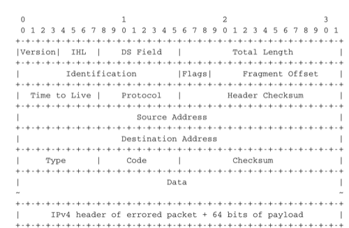
An ICMP message is composed of an 8 byte header, and a variable length
payload,
that usually contains the first bytes of the erroneous packet,
that triggered the transmission of the ICMP message.
ICMP is, like IP, host-to-host,
and so its packets are never delivered to a specific port,
even if they are sent in response to an error,
related to something sent from a port.
Individual UDP and TCP connections do not receive ICMP messages,
even when it would be helpful to get them.
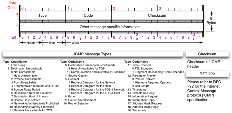
ICMP messages are identified by an 8-bit type field,
followed by an 8-bit subtype, or code.
The ICMP packet is encapsulated in an IPv4 packet.
The packet consists of header and data sections.
Only part of this diagram is the ICMP header:
The Type and Code fields indicate the
type of problem,
that was detected by the sender of the ICMP message.
The Checksum protects the entire ICMP message against
transmission errors.
The Data field contains additional information for some
ICMP messages.
To enable router discovery, the IRDP defines two kinds of ICMP
messages:
The ICMP Router Solicitation Message is sent from a computer host to
any routers on the local area network to request that they advertise
their presence on the network.
The ICMP Router Advertisement Message is sent by a router on the
local area network to announce its IP address as available for
routing.
And more.
04-NetworkData/detail_icmp_header.png
1.14.1.2 IPv6 ICMP
Unlike ICMPv4, ICMPv6 distinguishes between informational and error
messages by the first bit of the type field.
Unknown informational messages are simply dropped, while unknown
error messages must be handed off, if possible, to the appropriate
upper-layer process.
For example, [UDP] port unreachable messages are to be delivered to
the UDP sender of the undeliverable packet.
ICMPv6 includes an IPv6 version of Echo Request / Echo Reply, upon
which the ping6 command is based;
unlike with IPv4, arriving IPv6 echo-reply messages are delivered to
the process that generated the corresponding echo request.
ICMPv6 specifies two classes of messages: error messages that
indicate a problem in handling a packet.
The traditional utilisation of ICMPv6 is similar to ICMPv4.
ICMPv6 messages are carried inside IPv6 packets (the Next Header
field for ICMPv6 is 58).
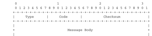
Each ICMP message contains an 8 bits header with a type field, a
code field and a 16 bits checksum computed over the entire ICMPv6
message.
The message body contains a copy of the IPv6 packet in error.
ICMPv6 specifies two classes of messages : error messages that
indicate a problem in handling a packet and informational messages. Four
types of error messages are defined in RFC 4443:
1: Destination Unreachable. Such an ICMPv6 message is sent when the
destination address of a packet is unreachable. The code field of the
ICMP header contains additional information about the type of
unreachability. The following codes are specified in RFC 4443
0: No route to destination. This indicates that the router that sent the
ICMPv6 message did not have a route towards the packet’s
destination
1: Communication with destination administratively prohibited. This
indicates that a firewall has refused to forward the packet towards its
destination.
2: Beyond scope of source address. This message can be sent if the
source is using link-local addresses to reach a global unicast address
outside its subnet.
3: Address unreachable. This message indicates that the packet reached
the subnet of the destination, but the host that owns this destination
address cannot be reached.
4: Port unreachable. This message indicates that the IPv6 packet was
received by the destination, but there was no application listening to
the specified port.
2: Packet Too Big. The router that was to send the ICMPv6 message
received an IPv6 packet that is larger than the MTU of the outgoing
link. The ICMPv6 message contains the MTU of this link in bytes. This
allows the sending host to implement Path MTU discovery RFC 1981
3: Time Exceeded. This error message can be sent either by a router
or by a host. A router would set code to 0 to report the reception of a
packet whose Hop Limit reached 0. A host would set code to 1 to report
that it was unable to reassemble received IPv6 fragments.
4: Parameter Problem. This ICMPv6 message is used to report either
the reception of an IPv6 packet with an erroneous header field (type 0)
or an unknown Next Header or IP option (types 1 and 2). In this case,
the message body contains the erroneous IPv6 packet and the first 32
bits of the message body contain a pointer to the error.
Two types of informational ICMPv6 messages are defined in RFC 4443 :
echo request and echo reply, which are used to test the reachability of
a destination by using ping6(8).
Ping is a computer network administration software utility used to
test the reachability of a host on an Internet Protocol (IP)
network.
Ping measures the round-trip time for messages sent from the
originating host to a destination computer that are echoed back to the
source.
Ping operates by sending Internet Control Message Protocol (ICMP)
echo request packets to the target host and waiting for an ICMP echo
reply.
The program reports errors, packet loss, and a statistical summary
of the results, typically including the minimum, maximum, the mean
round-trip times, and standard deviation of the mean.
Check out message format
1.14.1.3.2 Traceroute
$ man traceroute
$ man traceroute6
In class: check out wireshark of traceroute
packets
traceroute is a network diagnostic command for displaying the route
(path) and measuring transit delays of packets across an Internet
Protocol (IP) network.
The traceroute program uses ICMP Time Exceeded messages.
The time-to-live (TTL) value, also known as hop limit, is used in
determining the intermediate routers being traversed towards the
destination.
Traceroute sends packets with TTL values that gradually increase
from packet to packet, starting with TTL value of one.
Routers decrement TTL values of packets by one when routing and
discard packets whose TTL value has reached zero, returning the ICMP
error message ICMP Time Exceeded.
For the first set of packets, the first router receives the packet,
decrements the TTL value and drops the packet because it then has TTL
value zero.
The router sends an ICMP Time Exceeded message back to the
source.
The next set of packets are given a TTL value of two, so the first
router forwards the packets, but the second router drops them and
replies with ICMP Time Exceeded.
Proceeding in this way, traceroute uses the returned ICMP Time
Exceeded messages to build a list of routers that packets traverse,
until the destination is reached and returns an ICMP Destination
Unreachable message if UDP packets are being used or an ICMP Echo Reply
message if ICMP Echo messages are being used.
The sender expects a reply within a specified number of seconds. If
a packet is not acknowledged within the expected interval, an asterisk
is displayed.
1.14.1.4 Exploits
https://en.wikipedia.org/wiki/Ping_of_death
A correctly formed ping packet is typically 56 bytes in size, or 64
bytes when the ICMP header is considered, and 84 bytes including
Internet Protocol version 4 header.
However, any IPv4 packet (including pings) may be as large as 65,535
bytes.
Some computer systems were never designed to properly handle a ping
packet larger than the maximum packet size because it violates the
Internet Protocol.
Like other large but well-formed packets, a ping of death is fragmented
into groups of 8 octets before transmission.
However, when the target computer reassembles the malformed packet, a
buffer overflow can occur, causing a system crash and potentially
allowing the injection of malicious code.
https://en.wikipedia.org/wiki/Ping_flood
A ping flood is a simple denial-of-service attack where the attacker
overwhelms the victim with ICMP “echo request” (ping) packets.
This is most effective by using the flood option of ping which sends
ICMP packets as fast as possible without waiting for replies.
https://en.wikipedia.org/wiki/ICMP_tunnel
An ICMP tunnel establishes a covert connection between two remote
computers (a client and proxy), using ICMP echo requests and reply
packets.
An example of this technique is tunneling complete TCP traffic over ping
requests and replies.
ICMP tunneling can be used to bypass firewalls rules through obfuscation
of the actual traffic.
Depending on the implementation of the ICMP tunneling software, this
type of connection can also be categorized as an encrypted communication
channel between two computers. Without proper deep packet inspection or
log review, network administrators will not be able to detect this type
of traffic through their network.
ICMP-tunnels are sometimes used to circumvent firewalls that block
traffic between the LAN and the outside world.