Previous: 06-NetworkControl.html
document.querySelector('video').playbackRate = 1.2Look at section on encapsulation and layering for packet
details:
01-Overview.html
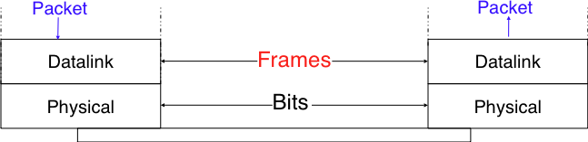
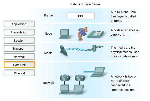
Now, we’re dealing with “Frames”
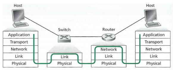
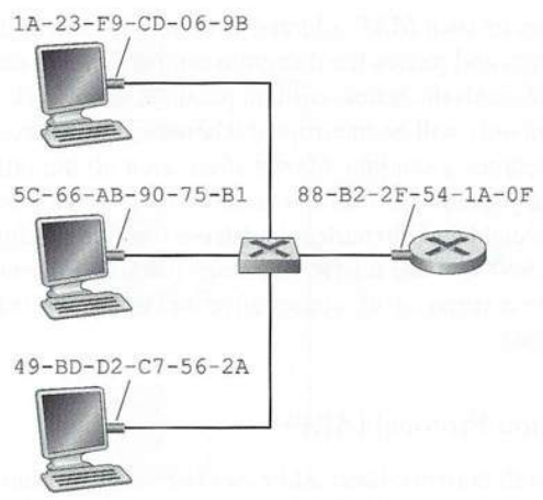
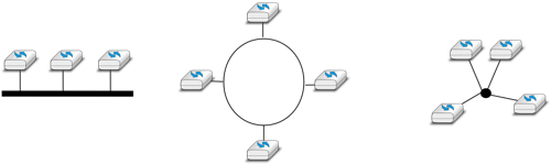
We are focusing on the LAN (Local Area Network):
Circle with x is router (network layer)
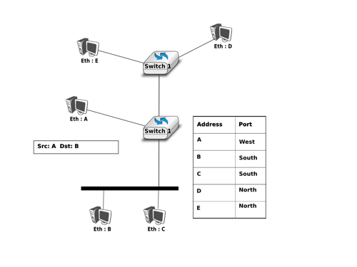
Squares with x are switches.
Lines between them are “links”.
Real physical links and transmission is noisy and un-reliable!
Within Ethernet, one data-link layer protocol
https://www.homenethowto.com/switching/ (great intro, review)
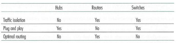
Switch
* A switch is more intelligent than an Ethernet hub, which simply
re-transmits packets out of every port of the hub except the port on
which the packet was received, unable to distinguish different
recipients, and achieving an overall lower network efficiency.
* A switch constantly monitors the traffic which is entering the switch
from connected devices.
* It then learns about where the different MAC addresses of those
devices are connected (port-MAC tuples, stored in its own table).
* It does this by looking at the traffic that arrives from computers, to
read MAC addresses of the traffic.
* A layer 2 network device is a multi-port device that uses hardware
addresses, MAC addresses, to process and forward data at the data link
layer (layer 2).
* They don’t need to send the same packet to every connected device, but
learn/know which MAC exists on which cable (port).
* So-called layer 3 and above switches exist, routing packets using
information at higher levels, but more simply than routers, for
example.
Switches learn the MAC address of the NICs attached to them, such
that they may direct traffic to each individual alone, rather than
broadcast.
Ask: What advantages does this provide?
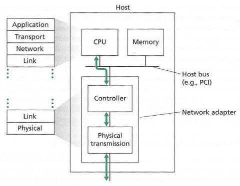
* link layer implemented in “adapter” (aka network interface card NIC)
or on a chip
* Ethernet card, 802.11 card; Ethernet chip-set
* implements link, physical layer
* attaches into host’s system buses
* combination of hardware, software, firmware

There are several reasons why hosts and router interfaces have MAC
addresses, in addition to network-layer addresses:
* First, LANs are designed for arbitrary network-layer protocols, not
just for IP and the Internet.
* If adapters were assigned IP addresses, rather than “neutral” MAC
addresses, then adapters would not easily be able to support other
network-layer protocols (for example, IPX or DECnet).
* Second, if adapters were to use network-layer addresses instead of MAC
addresses, the network-layer address would have to be stored in the
adapter RAM, and reconfigured every time the adapter was moved (or
powered up).
* Another option is to not use any addresses in the adapters and have
each adapter pass the data (typically, an IP datagram) of each frame it
receives up the protocol stack.
* The network layer could then check for a matching network-layer
address.
* One problem with this option is that the host would be interrupted by
every frame sent on the LAN, including by frames that were destined for
other hosts on the same broadcast LAN.
* In summary, in order for the layers to be largely independent building
blocks in a network architecture, different layers need to have their
own addressing scheme.
* We have now seen three types of addresses:
* host names for the application layer,
* port for the transport layer
* IP addresses for the network layer, and
* MAC addresses for the link layer.
Routers and computers have both IP and MAC addresses, but
switches have neither:
https://en.wikipedia.org/wiki/MAC_spoofing
* A MAC address may be referred to as a:
* Burned-in address
* Ethernet hardware address,
* hardware address, or
* physical address.
* Changing MAC addresses is necessary in network virtualization.
* Some modern operating systems, such as Apple iOS and Android,
especially in mobile devices, are designed to randomize the assignment
of a MAC address to network interface when scanning for wireless access
points to avert tracking systems.
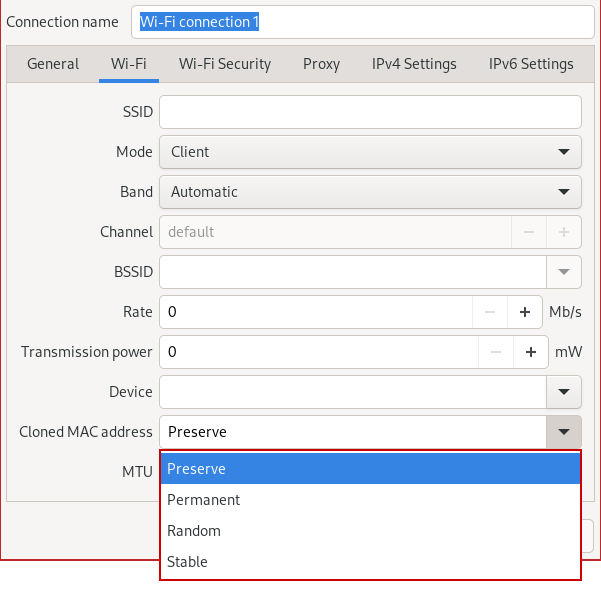
Option 1 (use network manager GUI)
#!/bin/bash

# automatic option 2: easy
sudo dnf install macchanger
man macchanger

# manual option 2: manual, deprecated, old
ifconfig <your device here> hw ether <XX:XX:XX:XX:XX:XX (your new mac address)>

# manual option 3: (modern)
ip link show
sudo ip link set dev <your device here> down
sudo ip link set dev <your device here> address <your new mac address>
sudo ip link set dev <your device here> up
According to Edward Snowden, the USA’s National Security Agency has a system that tracks the movements of mobile devices by monitoring MAC addresses: https://www.wired.com/2014/08/edward-snowden/
+++++++++++++ Cahoot-7-1
https://www.homenethowto.com/switching/arp-mac-ip/ (great! review this in class)
https://www.computer-networking.info/1st/html/network/network.html (ARP sections for IPv4 and NDP IPv6)
https://intronetworks.cs.luc.edu/current2/uhtml/ipv4.html#address-resolution-protocol-arp
https://www.practicalnetworking.net/series/arp/gratuitous-arp/
Summary of address resolution protocol (ARP):
The Address Resolution Protocol (ARP) is a communication protocol used for discovering a link layer address, such as a MAC address, associated with a given internet layer address, typically an IPv4 address.
Many different datalink technologies exist, and for each, ARP binds IPs to MACs.
The Address Resolution Protocol is a request-response protocol whose messages are encapsulated by a link layer protocol.
It is communicated within the boundaries of a single network, never routed across inter-networking nodes.
This property places ARP into the link layer of the Internet protocol suite.
In many ways, ARP is analogous to DNS, which resolves host names to IP addresses.
ip neigh, and one can actually send ARP requests with
arping#!/bin/bash
# See bottom of man page for sub-pages.
man ip
# What is your default gateway (network layer)
man ip-route
ip route help
# Example:
ip route
# manage/view ARP:
man ip-neighbour
ip neigh help
# Example
ip neigh show
ip -statswire neigh show
ip neigh add ...
ip neigh del ...
# clear cache
ip -stats -stats neigh flush all
# -s, -stats, -statistics
# Output more information.
# If the option appears twice or more, the amount of information increases.
# As a rule, the information is statistics or some time values.
# Send ARP request to a neighbour host
man arping
# Send ARP request to 192.168.1.1 via interface eth0
arping -I eth0 192.168.1.1
# Check for duplicate MAC addresses at 192.168.1.1 on eth0
arping -D -I eth0 192.168.1.1
# clear cache
ip -s -s neigh flush allNote these potential points of confusion:
* Depending on which interface you capture on, Wireshark may be giving
you synthesized ethernet-layer data (for example, Linux cooked
capture).
* If you sniffed real packets on the wire, you’d see the real
data.
* Make sure to capture to a real interface (eth0 for example) to get a
real capture.
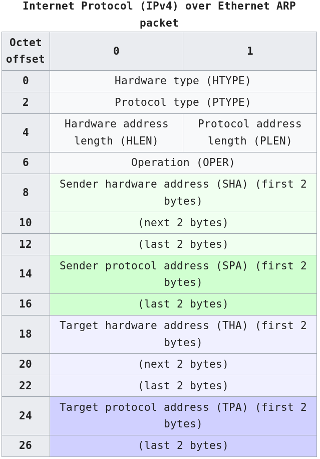
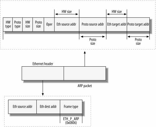
* Further, the ARP protocol has its own source and destination fields,
but they are used a little differently.
* For an ARP request the destination MAC in the ARP packet will be
00:00:00:00:00:00 instead of FF:FF:FF:FF:FF:FF.
* The all-zero mac is equivalent to unspecified.
* Is this confusing? Yea… it is.
* The source and destination MAC are present in both the Ethernet layer
and the ARP packet.
* And yes, they may be different.
* Gratuitous ARP packet has both, source and destination IP set to the
IP address of the device issuing the packet and the destination MAC is
the broadcast address ff:ff:ff:ff:ff:ff or 00:00:00:00:00:00 based on
the ARP implementation
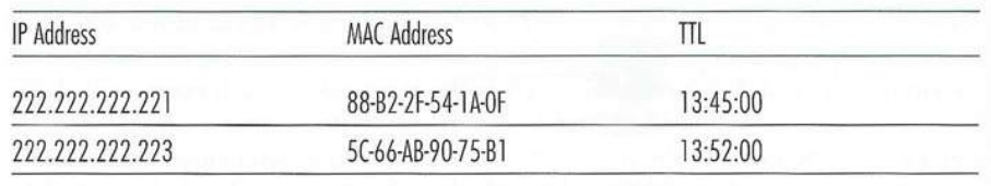
Note that a table does not necessarily contain an entry for every host
and router on the sub-net;
some may have never been entered into the table, and others may have
expired.
]
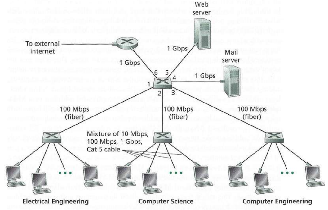
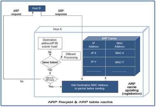
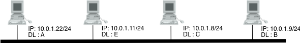
Two computers in an office (Computer 1 and Computer 2) are connected to each other in a local area network by Ethernet cables and network switches, with no intervening default gateways or routers.
Computer 1 has a packet to send to Computer 2.
Determines that Computer 2 has the IP address 192.168.0.55.
Use sub-net mask and/or CIDR network specification to determine whether this IP is on the same local network.
If this IP address belongs to the same sub-net, then the packet can be sent directly to its destination via the datalink layer service.
To send the message, it also requires Computer 2’s MAC address.
Each IPv4 host maintains an ARP cache containing the list of all mappings between IPv4 addresses and datalink layer addresses that it knows.
When an IPv4 hosts boots, its ARP cache is empty.
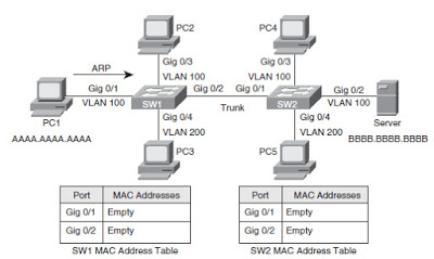
Thus the seeking computer first consults ARP cache.
First, Computer 1 uses a cached ARP table to look up 192.168.0.55 for any existing records of Computer 2’s MAC address (00:eb:24:b2:05:ac).
If the MAC address is found, it sends an Ethernet frame with destination address 00:eb:24:b2:05:ac, containing the IP packet onto the link.
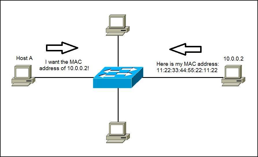
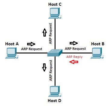
If the cache did not produce a result for 192.168.0.55, Computer 1 has to send a broadcast ARP request message (destination FF:FF:FF:FF:FF:FF MAC address), which is accepted by all computers on the local network, requesting an answer for 192.168.0.55’s MAC.
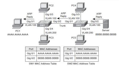
This broadcast frame is received by all devices on the LAN and only the host that owns the requested IPv4 address replies by returning a unicast ARP reply frame with the requested mapping.
Computer 2 responds with an ARP response message containing its MAC and IP addresses.
As part of fielding the request, Computer 2 may insert an entry for Computer 1 into its ARP table for future use.
Computer 1 receives and caches the response information, updates ARP table, and can now send the packet.
To deal with devices that move or whose addresses are reconfigured, most ARP implementations remove the cache entries that have not been used for a few minutes.
Some implementations re-validate ARP cache entries from time to time by sending ARP queries
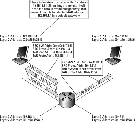
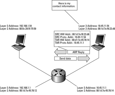
https://www.dummies.com/programming/networking/cisco/network-basics-remote-host-arp-requests/
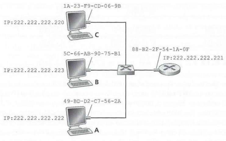
* A router has an IP address for each of its interfaces.
* For each router interface, there is also an ARP module (in the router)
and an adapter.
* Because the router below has two interfaces, it has two IP addresses,
two ARP modules, and two adapters.
* Of course, each adapter in the network has its own MAC address.
* A host determines whether an IP address either in or out of its local
sub-net by using the IP/sub-net mask/CIDR information.
* When a host needs to send an IPv4 packet to a destination outside of
its local sub-net, it must first send the packet to one of the routers
that reside on this sub-net.
* When the computer hoping to send a packet outside the sub-net boots,
its ARP cache will be empty.
* It must learn the IP address of its default external route (default
gateway router).
* It must also learn the MAC address of that default gateway router, to
send a packet to it, with an IP address of its final destination.
Detailed:
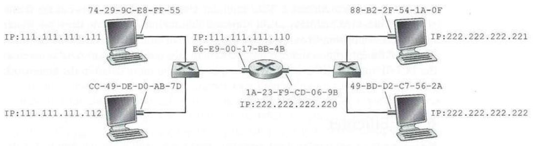
* in order for a datagram to go from 111.111.111.111 to a host on
sub-net 2, the datagram must first be sent to the router interface
111.111.111.110, which is the IP address of the first-hop router on the
path to the final destination.
* Thus, the appropriate MAC address for the frame is the address of the
adapter for router interface 111.111.111.110, namely, E6-E9-00-
17-BB-4B.
* How does the sending host acquire the MAC address for
111.111.111.110?
* By using ARP, of course!
* Once the sending adapter has this MAC address, it creates a frame
(containing the datagram addressed to 222.222.222.222) and sends the
frame into sub-net 1.
* The router adapter on sub-net 1 sees that the link-layer frame is
addressed to it, and therefore passes the frame to the network layer of
the router.
* Hooray, the IP datagram has successfully been moved from source host
to the router!
* But we are not finished.
* We still have to move the datagram from the router to the
destination.
* The router now has to determine the correct interface on which the
datagram is to be forwarded.
* This is done by consulting a forwarding table in the router.
* The forwarding table tells the router that the datagram is to be
forwarded via router interface 222.222.222.220.
* This interface then passes the datagram to its adapter, which
encapsulates the datagram in a new frame and sends the frame into
sub-net 2.
* This time, the destination MAC address of the frame is indeed the MAC
address of the ultimate destination.
* And how does the router obtain this destination MAC address?
* From ARP, of course!
https://www.homenethowto.com/basics/default-gateway-finding-other-ip-networks/
https://en.wikipedia.org/wiki/Default_gateway
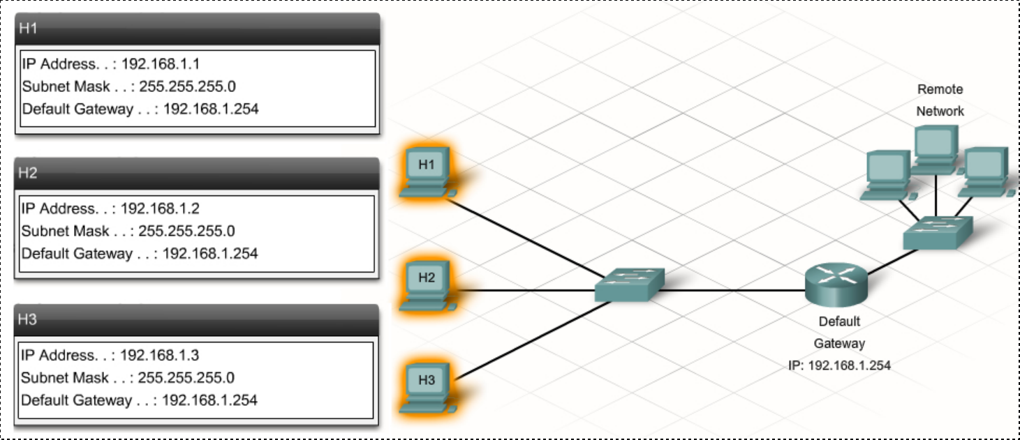
* A Gateway router that can connect to more than one IP network and can
route traffic between those IP networks.
* The router will have its own IP address on each IP network that it
connects to.
* A computer can only talk with other IP addresses within its own IP
network.
* So for the computer to be able to communicate via a router, at least
one of the router’s IP addresses must belong to the same IP network as
the computer.
* With the help of the Default Gateway address, the computers can then
find their way to all other IP networks in the whole world.
* The computer knows that it can talk directly with any other IP address
on the same IP network as itself.
* But as soon as it needs to talk to any other IP network it just needs
to send the traffic to the Default Gateway, which is the router.
* Then the router will take over responsibility for routing the traffic
towards the destination on the Internet.
* So you could say that by sending the traffic to the default gateway
the computer is delegating responsibility for forwarding the traffic to
the router.
* The computer will trust that the router can find the
destination.
* In turn, the home router will then trust the ISP’s routers to take
over responsibility for forwarding traffic further along the path toward
the destination.
Q: How does each machine know this sub-net information?
A: Either
1. it got it via DHCP when joining the network, or
2. it was manually configured.
When you configure an IP address manually on a computer you need to configure the same settings that a computer normally receives via DHCP:
* **IP address:**
    * on the same IP network as the router, and not already taken (available).
* **Subnet Mask:**
    * the same that the router is using
* **Default Gateway:**
    * which should be set to the LAN IP address of the router
* **DNS Server address:**
* either the router LAN IP address or another DNS server on the Internet. You may use the same address that the router normally hands out via DHCPWhen you observe observe an ARP request, update your cache for the
sender of that request:
* The above protocol is sufficient, but there is one further
point.
* When A sends its broadcast “who-has D?” ARP query, all other hosts C
check their own cache for an entry for A.
* If there is such an entry (that is, if A-IP is found there), then the
value for A-LAN is updated with the value taken from the ARP
message;
* if there is no pre-existing entry then no action is taken.
* This update process serves to avoid stale ARP-cache entries, which can
arise is if a host has had its Ethernet interface replaced.
* (USB Ethernet interfaces, in particular, can be replaced very
quickly.)
https://wiki.wireshark.org/Gratuitous_ARP
https://en.wikipedia.org/wiki/Address_Resolution_Protocol#ARP_announcements
Piggy-backs on greedy refreshing:
* Most hosts today implement self-ARP, or gratuitous ARP, on startup (or
wakeup):
* when station A starts up it sends out an ARP query for itself:
“who-has A?”.
* Two things are gained from this:
* first, all stations that had A in their cache are now updated with A’s
most current A-LAN address (due to greedy refreshing), in case there was
a change, and
* second, if an answer is received, then presumably some other host on
the network has the same IPv4 address as A.
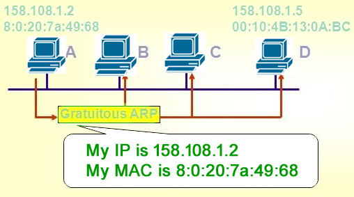
* ARP may also be used as a simple announcement protocol.
* This is useful for updating other hosts’ mappings of a hardware
address when the sender’s IP address or MAC address has changed.
* Such an announcement, also called a gratuitous ARP message, is usually
broadcast as an ARP request containing the SPA in the target field
(TPA=SPA), with THA set to zero.
* An alternative way is to broadcast an ARP reply with the sender’s SHA
and SPA duplicated in the target fields (TPA=SPA, THA=SHA).
* An ARP announcement is not intended to solicit a reply;
* instead it updates any cached entries in the ARP tables of other hosts
that receive the packet.
* Many operating systems perform gratuitous ARP during start-up.
* That helps to resolve problems which would otherwise occur if, for
example, a network card was recently changed (changing the
IP-address-to-MAC-address mapping) and other hosts still have the old
mapping in their ARP caches.
Reminder: 00:00:00:00:00:00 or ff:ff:ff:ff:ff:ff in the ARP header, turn
into ff:ff:ff:ff:ff:ff at link-layer header.
++++++++++++++ Cahoot-7-2
WHO HAS ANY GOOD ARP JOKES!?
HEY EVERYONE I HAVE A GRATUITOUS ARP JOKE!https://www.computer-networking.info/2nd/html/protocols/ipv6b.html (whole page)
https://intronetworks.cs.luc.edu/current2/uhtml/ipv6a.html#neighbor-discovery
In Internet Protocol Version 6 (IPv6) networks, the functionality of ARP is provided by the Neighbor Discovery Protocol (NDP).
The protocol defines five different ICMPv6 packet types to perform functions for IPv6 similar to the Address Resolution Protocol (ARP) and Internet Control Message Protocol (ICMP) Router Discovery and Router Redirect protocols for IPv4.
However, it provides many improvements over its IPv4 counterparts (RFC 4861, section 3.1).
For example, it includes Neighbor Unreachability Detection (NUD), thus improving robustness of packet delivery in the presence of failing routers or links, or mobile nodes.
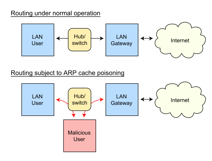
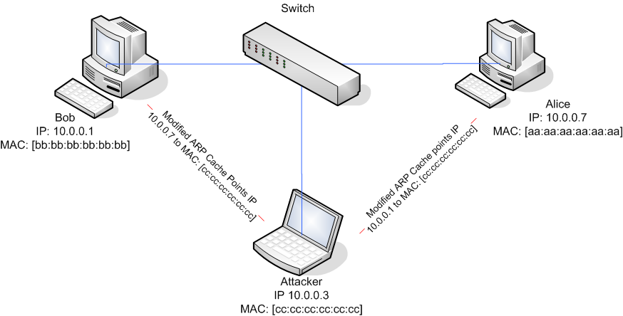
Example of 2:
Suppose A wants to log in to secure server S, using a password.
How can B (for Bad) impersonate S?
* Here is an ARP-based strategy, sometimes known as ARP Spoofing.
* First, B makes sure the real S is down, either by waiting until
scheduled downtime, or by launching a denial-of-service attack against
S.
* When A tries to connect, it will begin with an ARP “who-has S?”.
* All B has to do is answer, “S is-at B”.
* There is a trivial way to do this:
* B simply needs to set its own IP address to that of S.
* A will connect, and may be convinced to give its password to B.
* B now simply responds with something plausible like “backup in
progress; try later”, and meanwhile use A’s credentials against the real
S.
* This works even if the communications channel A uses is
encrypted!
* If A is using the SSH protocol, then A will get a message that the
other side’s key has changed
* B will present its own SSH key, not S’s.
* Unfortunately, many users (and even some IT departments) do not
recognize this as a serious problem.
* Some organizations, especially schools and universities, use personal
workstations with “frozen” configuration, so that the filesystem is
reset to its original state on every reboot.
* Such systems may be resistant to viruses, but in these environments
the user at A will always get a message to the effect that S’s
credentials are not known.
In the past, the cache timeout interval was around 10 minutes, but Linux systems now use a much smaller timeout (~30 seconds observed in 2012).
https://en.wikipedia.org/wiki/ARP_spoofing
https://en.wikipedia.org/wiki/Proxy_ARP
12-LanHacking.html (see code at
end of page for how.html)
If you don’t like my ARP jokes, I’ll just blame them on
someone else.
I like ARP jokes, because it’s so easy to make them appear to originate
from other people.
Use Snort, that you set up earlier:
https://en.wikipedia.org/wiki/Snort_(software)
https://en.wikipedia.org/wiki/Promiscuous_mode
* Normally, your NIC will only pass up packets to the OS that are
directed to its MAC.
* However, you can put your NIC in promiscuous mode, to grab all the
packets.
* Finally, there is an interesting use of ARP to detect Ethernet
password sniffers (generally not quite the issue it once was, due to
encryption and switching).
* To find out if a particular host A is in promiscuous mode, send an ARP
“who-has A?” query.
* Address it not to the broadcast Ethernet address, though, but to some
nonexistent Ethernet address.
* If promiscuous mode is off, A’s network interface will ignore the
packet.
* But if promiscuous mode is on, A’s network interface will pass the ARP
request to A itself, which is likely then to answer it.
* This is one reason wireshark needs sudo
https://www.computer-networking.info/1st/html/lan/lan.html (theory and protocols, link too)
https://www.computer-networking.info/2nd/html/principles/reliability.html#the-datalink-layer (theory)
https://www.computer-networking.info/2nd/html/protocols/lan.html (protocols)
https://intronetworks.cs.luc.edu/current2/uhtml/ethernet1.html
https://intronetworks.cs.luc.edu/current2/uhtml/ethernet2.html
https://intronetworks.cs.luc.edu/current2/uhtml/otherLANs.html
Last layer was network, next is link, then physical.
data-link layer bridges that gap.
The data link layer has two sub-layers:
1. logical link control (LLC) and
2. media access control (MAC).
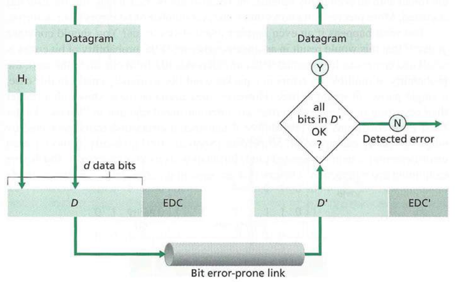
Error control:
* errors caused by signal attenuation and noise.
* receiver detects presence of errors:
* and either
* signals sender for re-transmission, or
* drops frame
* or, receiver identifies and corrects bit error(s) without resorting to
re-transmission
Flow control
* in addition to the one provided on the transport layer.
* Data-link-layer flow control is not used in LAN protocols such as
Ethernet, but is in modems and wireless networks.
* pacing between adjacent sending and receiving nodes.
https://en.wikipedia.org/wiki/Logical_link_control
https://en.wikipedia.org/wiki/Error_detection_and_correction
https://en.wikipedia.org/wiki/Error-correcting_code
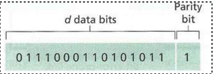
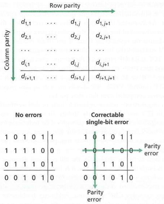
We can actually recover from some errors.
https://en.wikipedia.org/wiki/Parity_bit
https://en.wikipedia.org/wiki/Cyclic_redundancy_check
See details
Not in Ethernet, but it is in other protocols.
Lessons in life and networking:
“Give everyone a chance to speak.”
“Don’t monopolize the conversation.”
“Raise your hand if you have a question.”
“Don’t interrupt when someone is speaking.”
“Don’t speak until you are spoken to.”
“Don’t fall asleep when someone is talking.”
Three broad classes:
* Taking turns
* nodes take turns, but nodes with more to send can take longer
turns
* Channel partitioning
* divide channel into smaller “pieces” (time slots, frequency,
code)
* allocate piece to node for exclusive use
* Random access
* channel not divided, allow collisions
* “recover” from collisions
Apply to many types of network structures:
https://en.wikipedia.org/wiki/Polling_(computer_science)
https://en.wikipedia.org/wiki/Master/slave_(technology)
Have a coordinator.
* Controller node “invites” Agent
nodes to transmit in turn
* Concerns:
* polling overhead
* latency
* single point of failure (Controller)
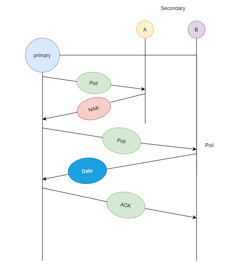
In the first diagram, we see that primary station asks station A if
it has any data ready for transmission, since A does not have any data
queued for transmission it sends a Poll Reject or NAK (negative
acknowledgment), and then it asks station B, since B has data ready for
transmission, so it transmits the data and in return receives
acknowledgment from primary station.
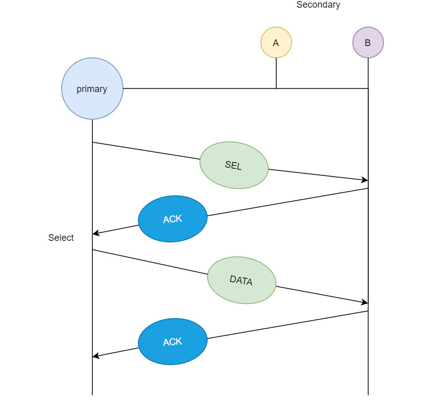
If primary station wants to send data to the secondary stations, it
sends a select (sel) message, and if the secondary
station accepts the request from the primary station, then it sends back
an acknowledgment and then primary station transmits the data and in
return receives an acknowledgment.
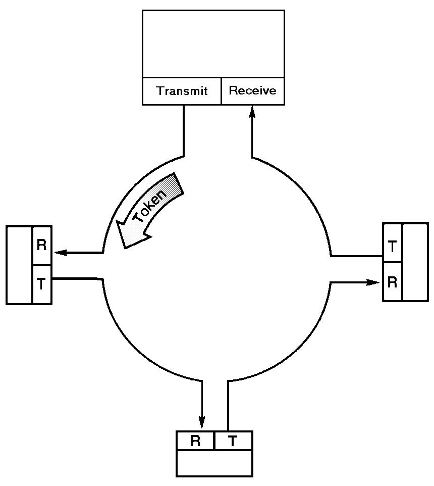
https://en.wikipedia.org/wiki/Token_passing
https://en.wikipedia.org/wiki/Token_ring
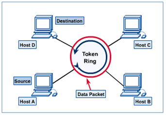
Take turns!
* control token passed from one node to next sequentially.
* token message
* Every computer listens on the shared “circular” bus.
* concerns:
* token overhead
* latency
* single point of failure (token)
It’s like each node is token, but only one at a time, as the pass the
… token.
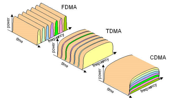
In telecommunications and computer networks, a channel access method or multiple access method allows more than two terminals connected to the same transmission medium to transmit over it and to share its capacity.
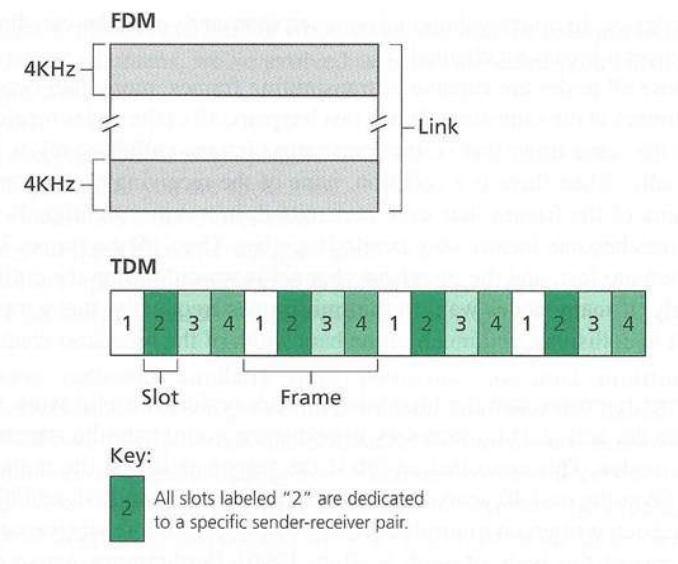
https://en.wikipedia.org/wiki/Frequency-division_multiple_access
* FDMA: frequency division multiple access
* channel spectrum divided into frequency bands
* each station assigned fixed frequency band
* unused transmission time in frequency bands go idle
https://en.wikipedia.org/wiki/Time-division_multiple_access
* TDMA: time division multiple access
* access to channel in “rounds”
* each station gets fixed length slot (length = packet transmission
time) in each round
* unused slots go idle
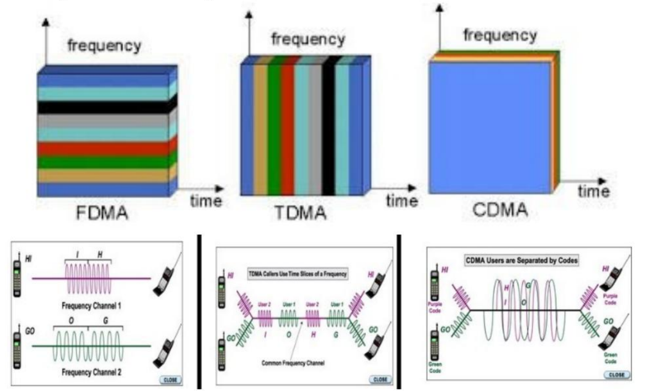
https://en.wikipedia.org/wiki/Code-division_multiple_access
To share media, CDMA employs spread spectrum technology and a special
coding scheme (where each transmitter is assigned a code).
(statistical methods)
* https://en.wikipedia.org/wiki/Statistical_time-division_multiplexing
* https://en.wikipedia.org/wiki/Medium_access_control
* https://en.wikipedia.org/wiki/Channel_access_method#Common_multiple_access_protocols
Assumes collisions will happen, but random access MAC protocol
specifies:
* how to detect collisions
* how to recover from collisions (e.g., via delayed
re-transmissions)
https://en.wikipedia.org/wiki/ALOHAnet
Assumptions:
* all frames same are the same size
* time is divided into equal size slots (time to transmit 1 frame)
* nodes start to transmit only at the slot beginning
* nodes are synchronized
* if 2 or more nodes transmit in a given slot, then all nodes detect
collision
Operation:
* when a node obtains a fresh frame, it transmits in the next available
slot
* if no collision:
* node can send new frame in next slot
* if collision:
* node re-transmits frame in each subsequent slot, with probability p,
until success
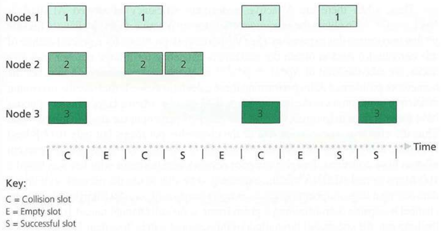
Nodes 1, 2, and 3 collide in the first slot.
Nodes 1 and 2 collide in the third slot.
Node 2 finally succeeds in the fourth slot.
Node 1 and 3 collide in the sixth slot.
Node 1 succeeds in the eighth slot.
Node 3 succeeds in the ninth slot.
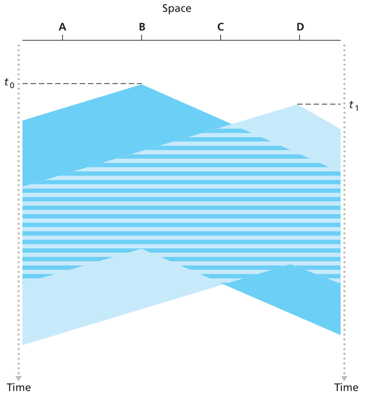
https://en.wikipedia.org/wiki/Carrier-sense_multiple_access
* Under CSMA, a transmitter uses a carrier-sense mechanism to determine
whether another transmission is in progress before initiating a
transmission.
* That is, it tries to detect the presence of a carrier signal from
another node before attempting to transmit.
* If a carrier is sensed, the node waits for the transmission in
progress to end before initiating its own transmission.
* Using CSMA, multiple nodes may, in turn, send and receive on the same
medium.
* Transmissions by one node are generally received by all other nodes
connected to the medium.
Carrier-sensing: listen before transmit.
https://en.wikipedia.org/wiki/Carrier-sense_multiple_access_with_collision_avoidance

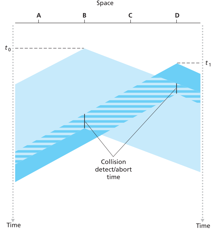
CSMA/CD: carrier sensing, multiple-access, deferral as in CSMA
* collisions detected within short time
* colliding transmissions aborted, reducing channel wastage
* collision detection:
* easy in wired LANs: measure signal strengths, compare transmitted,
received signals
* difficult in wireless LANs: received signal strength overwhelmed by
local transmission strength
* human analogy: the polite conversationalist
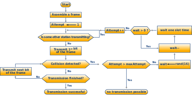
Ethernet CSMA/CD algorithm: exponential
back-off
* NIC receives datagram from network layer, creates frame
* if NIC senses channel idle,
* starts frame transmission.
* else NIC senses channel busy,
* waits until channel idle, then transmits.
* If NIC transmits entire frame without detecting another transmission,
NIC is done with frame!
* If NIC detects another transmission while transmitting, aborts and
sends jam signal
* After aborting, NIC enters binary (exponential) back-off:
* after collision, NIC chooses K at random from {0, 1, 2, …,
2m-1){width=700px.
* NIC waits K*512 bit times, returns to Step 2 longer back-off interval
with more collisions
+++++++++++++ Cahoot-7-3
https://en.wikipedia.org/wiki/Ethernet
https://en.wikipedia.org/wiki/Medium_access_control
https://hackaday.com/2023/11/07/all-about-cats-and-what-ethernet-classifications-mean-beyond-bigger-number-better/
Note: discussions above were actually just about ONE datalink protocol
(including switches).
Modern switched Ethernet:
connection-less:
* no handshaking between sending and receiving NICs
unreliable:
* receiving NIC does not send acks or nacks to sending NIC
* data in dropped frames recovered only if initial sender uses higher
layer rdt (e.g., TCP), otherwise dropped data lost
Ethernet’s MAC protocol:
* un-slotted CSMA/CD with binary back-off
https://en.wikipedia.org/wiki/Ethernet_frame
sending adapter encapsulates IP datagram (or other network layer
protocol packet) in Ethernet frame
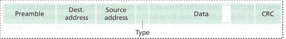
preamble (more details about why below):
* 7 bytes with pattern 10101010 followed by one byte with pattern
10101011
* used to synchronize receiver, sender clock rates
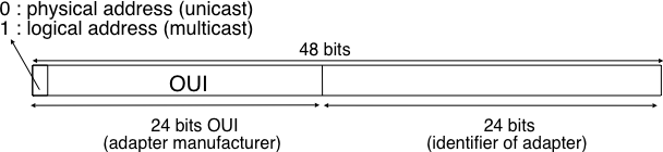
addresses:
* 6 byte source, destination MAC addresses
* if adapter receives frame with matching destination address, or with
broadcast address (e.g. ARP packet), it passes data in frame to network
layer protocol
* otherwise, adapter discards frame
type:
* indicates higher layer protocol (mostly IP but others possible, e.g.,
Novell IPX, AppleTalk)
Data/payload:
* The minimum payload is 42 octets when an 802.1Q tag is present and 46
octets when absent.
* When the actual payload is less, padding bytes are added
accordingly.
* The maximum payload is 1500 octets.
* Non-standard jumbo frames allow for larger maximum payload size.
CRC:
* cyclic redundancy check at receiver
* error detected: frame is dropped
* The frame check sequence (FCS) is a four-octet cyclic redundancy check
(CRC) that allows detection of corrupted data within the entire frame as
received on the receiver side.
* The FCS value is computed as a function of the protected MAC frame
fields:
* source and destination address,
* length/type field,
* MAC client data, and
* padding (that is, all fields except the FCS)
* The checksum/CRC is computed by the sender and placed in the frame
before applying bit stuffing.
* Where should the CRC be located in a frame ?
* The transport and datalink layers usually chose different strategies
to place their CRCs or checksums.
* Transport layer protocols usually place their CRCs or checksums in the
segment header.
* Datalink layer protocols sometimes place their CRC in the frame
header, but often in a trailer at the end of the frame.
* This choice reflects implementation assumptions, but also influences
performance RFC 893.
* When the CRC is placed in the trailer, as in Ethernet, the datalink
layer can compute it while transmitting the frame and insert it at the
end of the transmission.
* All Ethernet interfaces use this optimization today.
* When the checksum is placed in the header, as in a TCP segment, it is
impossible for the network interface to compute it while transmitting
the segment.
* Some network interfaces provide hardware assistance to compute the TCP
checksum, but this is more complex than if the TCP checksum were placed
in the trailer
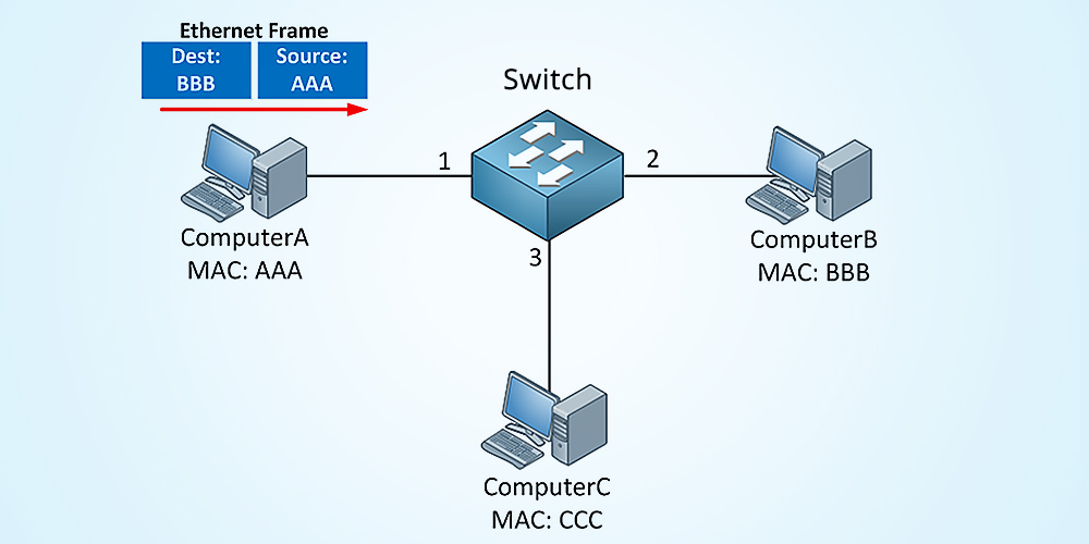
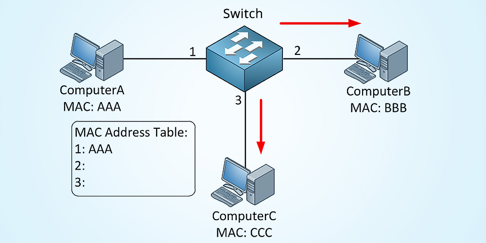
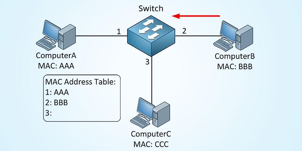
A switch table is built automatically, dynamically, and autonomously
without any intervention from a network administrator or from a
configuration protocol.
In other words, switches are self-learning.
This capability is accomplished as follows:
1. The switch table is initially empty.
2. For each incoming frame received on an interface, the switch stores
in its table (1) the MAC address in the frame’s source address field,
(2) the interface from which the frame arrived, and (3) the current
time. In this manner the switch records in its table the LAN segment on
which the sender resides. If every host in the LAN eventually sends a
frame, then every host will eventually get recorded in the table.
3. The switch deletes an address in the table if no frames are received
with that address as the source address after some period of time (the
aging time). In this manner, if a PC is replaced by another PC (with a
different adapter), the MAC address of the original PC will eventually
be purged from the switch table.
both are store-and-forward:
routers: network-layer devices (examine network-layer headers)
switches: link-layer devices (examine link-layer headers)
both have forwarding tables:
routers: compute tables using routing algorithms, IP addresses
switches: learn forwarding table using flooding, learning, MAC
addresses
If you want to watch all packets on a network (like you can on
wireless anyway), you can force a wired switch to broadcast all,
then:
* send tons of packets to the switch with many different bogus source
MAC addresses, thereby filling the switch table with bogus entries and
leaving no room for the MAC addresses of the legitimate hosts.
* This causes the switch to broadcast most frames, which can then be
picked up by the sniffer.
Switches must have ports turned off and not configured in loops, so that broadcasts don’t create broadcast storms.
https://en.wikipedia.org/wiki/Virtual_LAN
https://en.wikipedia.org/wiki/Multiprotocol_Label_Switching
Despite the different semantics of layering in TCP/IP and OSI, the link layer is sometimes described as a combination of the data link layer (layer 2) and the physical layer (layer 1) in the OSI model.
https://en.wikipedia.org/wiki/Link_layer (next 1/2 down)
https://www.computer-networking.info/1st/html/lan/lan.html (show)
https://intronetworks.cs.luc.edu/current2/uhtml/links.html (show)
https://intronetworks.cs.luc.edu/current2/uhtml/packets.html
http://intronetworks.cs.luc.edu/current2/uhtml/otherLANs.html
At the lowest (logical) level, network links look like serial lines.
In this chapter we address how packet structures are built on top of serial lines, via encoding and framing.
Encoding determines how bits and bytes are represented on a serial line; framing allows the receiver to identify the beginnings and endings of packets.
How does a sender encode frames so that the receiver can efficiently extract them from the stream of bits that it receives from the physical layer?
Two related points:
Next: 08-Wireless.html