Previous: 02-Application.html
document.querySelector('video').playbackRate = 1.2“Now, if someone tries to monopolize the Web,
for example pushes proprietary variations on network protocols,
then that would make me unhappy.”
- Tim Berners-Lee
https://www.accessnow.org/keepiton/ (good animation no
longer posted).
https://www.accessnow.org/elections-internet-shutdowns-watch-2022/
https://www.accessnow.org/cms/assets/uploads/2022/06/A-taxonomy-of-internet-shutdowns-the-technologies-behind-network-interference.pdf
Review methods.
https://www.theregister.com/2022/10/06/great_firewall_of_china_upgrades/
https://www.encryptallthethings.net/
and as many layers as you can,
ideally, from the IP-layer, all the way up,
via IPSec.
Review by glancing back now at section on encapsulation and
layering:
01-Overview.html
Reading:
Book
3.1-3.2
IntroNetworks
http://intronetworks.cs.luc.edu/current2/uhtml/intro.html#transport
Computer-Networking
https://www.computer-networking.info/1st/html/transport/principles.html
https://www.computer-networking.info/2nd/html/protocols/transport.html
Wikipedia
https://en.wikipedia.org/wiki/Transport_layer
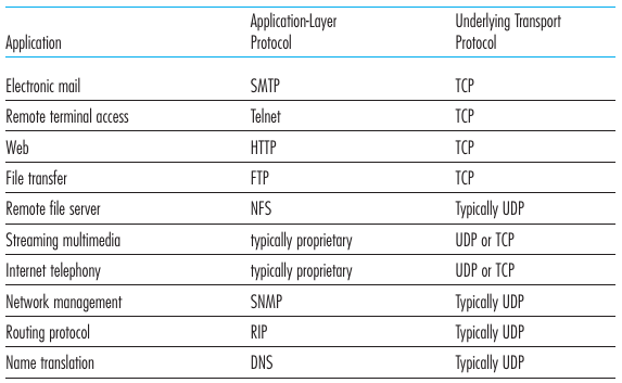
Application usage of transport layer protocols
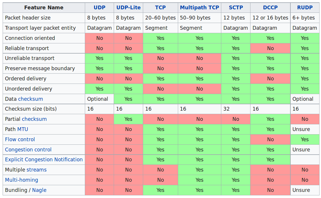
Transport layer is more than TCP and UDP
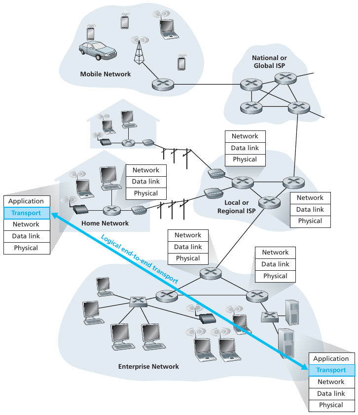
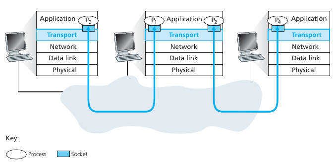
Application and network layers are end-end
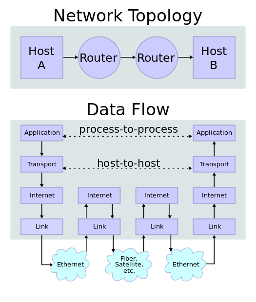
Note: Transport facilitates process-to-process connections.
Transport layer services are conveyed to an application via a programming interface to the transport layer protocols.
Multiplexing:
Connection-oriented communication:
It is normally easier for an application to interpret a connection as a
data stream rather than having to deal with the underlying
connection-less models, such as the datagram model of the User Datagram
Protocol (UDP) and of the Internet Protocol (IP).
Same order delivery:
Reliability:
Flow control:
Congestion avoidance:
https://en.wikipedia.org/wiki/Port_(computer_networking)
In computer networking, a port is a communication
endpoint.
At the software level, within an operating system,
a port is a logical construct that identifies a
specific process or a type of network service.
Each port number is a 16-bit number, ranging from 0 to 65535.
The port numbers ranging from 0 to 1023 are called well-known port numbers and are restricted, which means that they are reserved for use by well-known application protocols such as
At the software level, within an operating system, a port is a logical construct that identifies a specific process or a type of network service.
The list of well-known port numbers is given in RFC 1700 and is updated at
Check out on Linux:
$ vimx /etc/servicesAs the port numbers are encoded as a 16 bits field, there can be up to only 65535 different server processes that are bound to a different UDP port at the same time on a given server.
Privileged port numbers
(1 < port < 1024)
In most Unix variants, only processes having system administrator
privileges can be bound to port numbers smaller than 1024.
Ephemeral port numbers
(officially 49152 <= port <= 65535)
Registered port numbers
(officially 1024 <= port < 49152)
Port numbers are sometimes seen in web or other uniform resource
locators (URLs).
By default, HTTP uses port 80 and HTTPS uses port 443,
but a URL like http://www.example.com:8080/path/
specifies that the web browser connects instead to port 8080 of the HTTP
server.
https://en.wikipedia.org/wiki/Port_scanner
https://nmap.org/book/tcpip-ref.html
sudo apt/dnf/zypper/etc install nmap+++++++++++++++++++++++++++++++++
Cahoot-03-0
nmap web.mst.edu
Watch this with Wireshark
Mention:
https://shodan.io
does extensive port-scanning
https://en.wikipedia.org/wiki/Port_scanner#Types
TCP scan
SYN scan
UDP scan
ACK scan
Window scan
FIN scan
and more…
https://en.wikipedia.org/wiki/Multiplexing
Multiplexing at the transport layer refers merely to the mixing and un-mixing of traffic with different (port, IP) tuples for source and destination addresses.
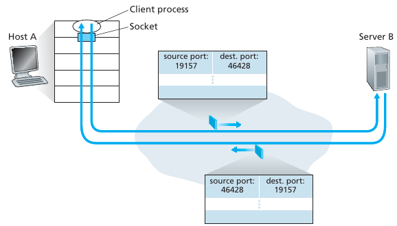
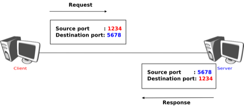
Transport-layer multiplexing and de-multiplexing
Web server and two clients
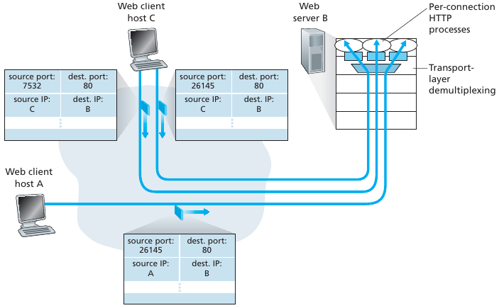
While destination (IP, port) tuples are the same, the source (IP, port)
tuples differ for each client.
Handle data from multiple sockets,
add transport header including source (IP, port) tuple,
and destination (IP, port) tuple,
used for de-multiplexing at the destination,
and on response back to the source.
Use header info to deliver received segments to correct process, and correct socket within the process.
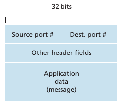
Source and destination port-numbers in segment
I heard a great UDP joke the other day….
You might not get it.
Reading:
Book
Chapter 3.3-3.4
IntroNetworks
http://intronetworks.cs.luc.edu/current2/uhtml/udp.html
Computer-Networking
https://www.computer-networking.info/1st/html/transport/udp.html
https://www.computer-networking.info/2nd/html/protocols/udp.html
https://en.wikipedia.org/wiki/User_Datagram_Protocol
https://en.wikipedia.org/wiki/Datagram_Transport_Layer_Security
(UDP encryption)
IETF
https://tools.ietf.org/html/rfc768
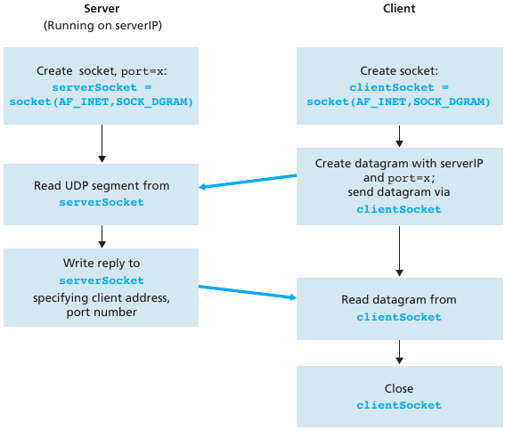
recall: when creating datagram to send into UDP socket,
must specify destination IP address destination port #
The best thing about UDP jokes is that I don’t care if you get them or not.
I had another funny UDP joke to tell,
but I lost it somewhere…
Reminder:
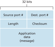
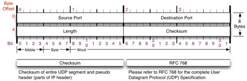
UDP segment structure:
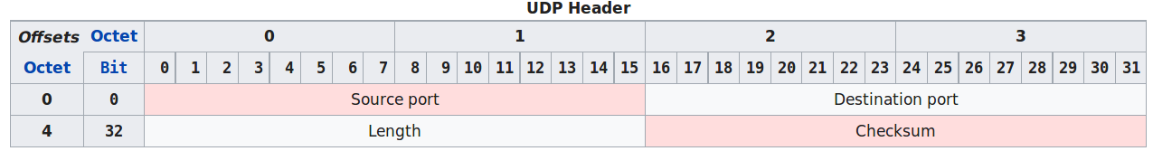
* The UDP header contains four fields:
* a 16 bits source port
* a 16 bits destination port
* a 16 bits length field
* a 16 bits checksum
Source port number:
Sender’s port; should be assumed to be the port to reply to if
needed.
If the source host is the client,
then the port number is likely to be an ephemeral port number.
If the source host is the server,
then the port number is likely to be a well-known port number.
Destination port number:
Receiver’s port is required.
Similar to source port number, if the client is the destination
host,
then the port number will likely be an ephemeral port number,
and if the destination host is the server,
then the port number will likely be a well-known port number.
Length:
Specifies the length in bytes of the UDP header and UDP data.
The minimum length is 8 bytes because that is the length of the
header.
Data length, which is imposed by the underlying IPv4 protocol,
is 65,507 bytes (65,535 - 8 byte UDP header - 20 byte IP header).
Checksum:
May be used for error-checking of the header and data.
This field is optional in IPv4, and mandatory in IPv6.
The field carries all-zeros if unused.
I’d make another joke about UDP,
but I don’t know if anyone’s actually listening…
Goal: detect “errors” (e.g., flipped bits) in transmitted segment
http://intronetworks.cs.luc.edu/current2/uhtml/packets.html#error-detection
* You may wonder why UDP provides a checksum in the first place, as many
link layer protocols (including the popular Ethernet protocol) also
provide error checking.
* There is no guarantee that all the links between source and
destination provide error checking
* one of the links may use a link-layer protocol that does not provide
error checking.
* Even if segments are correctly transferred across a link, it’s
possible that bit errors could be introduced when a segment is stored in
a router’s memory.
* Given that neither link-by-link reliability nor in-memory error
detection is guaranteed, UDP must provide error detection at the
transport layer, on an end-end basis, if the end-end data transfer
service is to provide error detection.
* The checksum at this level is an example of the celebrated end-end
principle in system design [Saltzer 1984], which states that since
certain functionality (error detection, in this case) should be
implemented on an end-end basis:
* “functions placed at the lower levels may be redundant or of little
value when compared to the cost of providing them at the higher
level.”
* UDP does not do anything to recover from an error.
* Some implementations of UDP simply discard the damaged segment; others
pass the damaged segment to the application with a warning.
Pseudo-header the checksum is taken over:
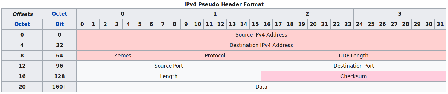
* The source and destination addresses are those in the IPv4
header.
* The protocol is that for UDP (see List of IP protocol numbers): 17
(0x11).
* The UDP length field is the length of the UDP header and data. The
field data stands for the transmitted data.
* UDP checksum computation is optional for IPv4.
* If a checksum is not used it should be set to the value zero.
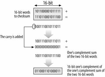
* Checksum uses the 1s complement: https://en.wikipedia.org/wiki/Ones%27_complement
* 1s complement of the sum of all the 16-bit words in the segment, such
that adding back the checksum to the same input will produce
111111111…
* The ones’ complement of a binary number is defined as the value
obtained by inverting all the bits in the binary representation of the
number (swapping 0s for 1s and vice versa).
* The ones’ complement of the number then behaves like the negative of
the original number in some arithmetic operations.
As an example, suppose that we have the following three 16-bit words:
0110011001100000
0101010101010101
1000111100001100
The sum of first two of these 16-bit words is
0110011001100000
0101010101010101
__________
1011101110110101
Adding the third word to the above sum gives
1011101110110101
1000111100001100
__________
0100101011000010The checksum of the UDP segment is computed over a pseudo header
containing:
the source IP address,
the destination IP address and
a 32 bits bit field containing the most significant byte set to 0,
the second set to 17,
and the length of the UDP segment in the lower two bytes.
the entire UDP segment, including its header
Ask:
UDP checksum pseudo header includes IP addresses (which are normally in
network layer), why?
+++++++++++++++++++++++ Cahoot-03-1
Are any others of these disadvantages?
If we assume there are bad network citizens?
I once told an NTP joke.
The timing was perfect…
The punchline often arrives before the set-up.
Do you know the problem with UDP jokes?
+++++++++++++++++++++++ Cahoot-03-2
nc (netcat) can also serve to explore UDP functionality (-u is
udp)
$ nc -u serverurl
Re-demonstrate with Wireshark:
socket_UDP_server.py, socket_UDP_client.py, nc -u, nslookup
Let’s begin to think about TCP:
Re-demonstrate with Wireshark:
socket_TCP_server_mt.py, socket_TCP_client_mt.py, ncat, traceroute, web
browser, ncat
Some things to observe:
(theory)
Reliable data transfer
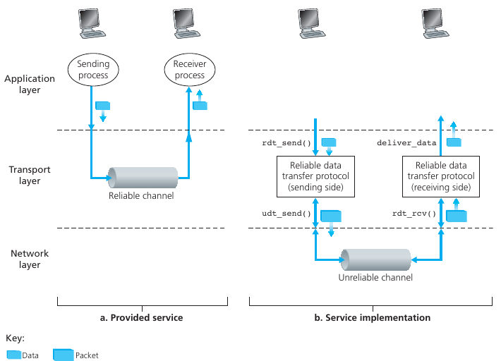
How to implement the black frames boxes above?
Checksum
Used to detect bit errors in a transmitted packet.
Timer (timeout)
Used to timeout/re-transmit a packet, possibly because the packet (or
its ACK) was lost within the channel.
Because timeouts can occur when a packet is delayed but not lost
(premature timeout),
or when a packet has been received by the receiver, but the
receiver-to-sender ACK has been lost,
duplicate copies of a packet may be received by a receiver.
Sequence number
Used for sequential numbering of packets of data flowing from sender to
receiver.
Gaps in the sequence numbers of received packets allow the receiver to
detect a lost packet.
Packets with duplicate sequence numbers allow the receiver to detect
duplicate copies of a packet.
Acknowledgment
Used by the receiver to tell the sender that a packet or set of packets
has been received correctly.
Acknowledgments will typically carry the sequence number of the packet
or packets being acknowledged. Acknowledgments may be individual or
cumulative, depending on the protocol.
Negative acknowledgment
Used by the receiver to tell the sender that a packet has not been
received correctly.
Negative acknowledgments will typically carry the sequence number of the
packet that was not received correctly.
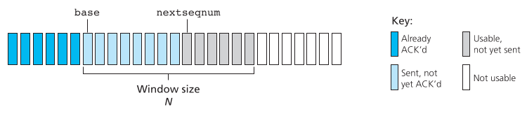
Window, pipelining
Note: These two are more like speed-enhancing mechanisms for
compensating for reliability mechanisms.
The sender may be restricted to sending only packets with sequence
numbers that fall within a given range.
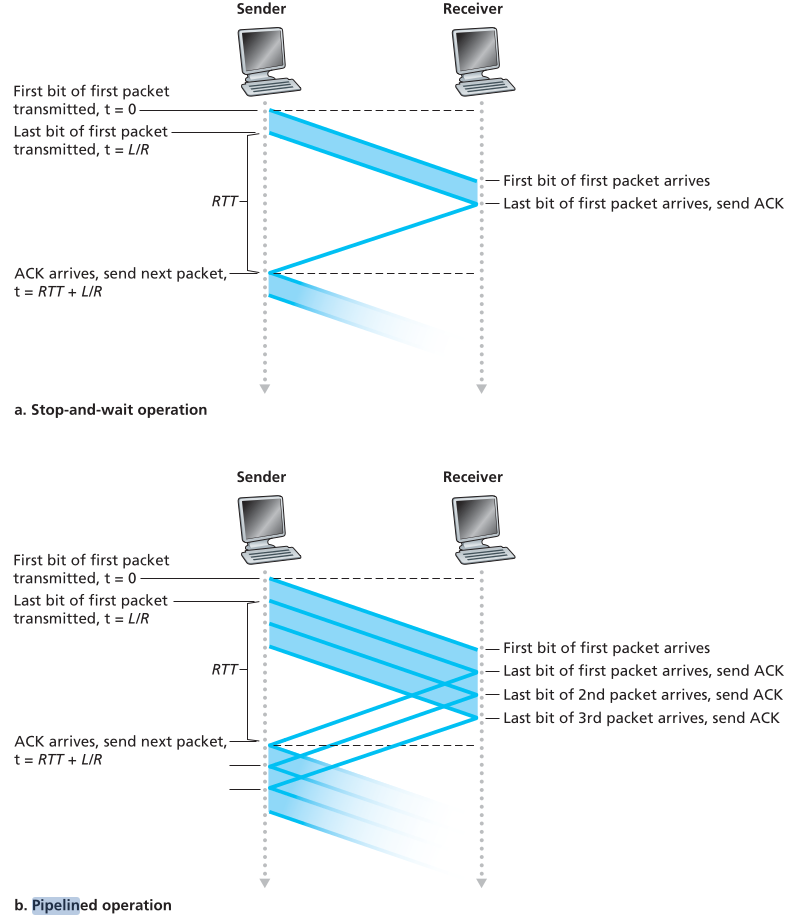
By allowing multiple packets to be transmitted but not yet acknowledged,
sender utilization can be increased over a stop-and-wait mode of
operation.
We’ll see shortly that the window size may be set on the basis of the
receiver’s ability to receive and buffer messages, or the level of
congestion in the network, or both.
More to come in protocol operation (below).
This is about how the next part covering TCP will feel:
“Hi, I’d like to hear a TCP joke”
“Hello, would you like to hear a TCP joke”
“Yes, I’d like to hear a TCP joke”
“OK, I’ll tell you a TCP joke”
“OK, I’ll hear a TCP joke”
“Are you ready to hear a TCP joke”
“Yes, I’m ready hear a TCP joke”
“OK, I’m about to send a TCP joke. It will last 10 seconds, it has two
characters, it doesn’t have a setting, it ends with a punchline”
“Ok, I’m ready to hear a TCP joke that will last 10 seconds, has two
characters, has no explicit setting and ends with a punchline”
“I’m sorry, your connection has timed out,
… Hello, Would you like to hear a TCP joke”
Reading:
Book
Chapter 3.5-3.8
IntroNetworks
http://intronetworks.cs.luc.edu/current2/uhtml/
http://intronetworks.cs.luc.edu/current2/uhtml/tcpA.html
(read)
http://intronetworks.cs.luc.edu/current2/uhtml/tcpB.html
http://intronetworks.cs.luc.edu/current2/uhtml/reno.html
http://intronetworks.cs.luc.edu/current2/uhtml/dynamicsA.html
http://intronetworks.cs.luc.edu/current2/uhtml/dynamicsB.html
http://intronetworks.cs.luc.edu/current2/uhtml/newtcps.html
Computer-Networking
https://www.computer-networking.info/1st/html/transport/tcp.html
https://www.computer-networking.info/2nd/html/protocols/tcp.html
Wikipedia
https://en.wikipedia.org/wiki/Transmission_Control_Protocol
IETF
https://tools.ietf.org/html/rfc7414
RFCs: 793, 1122, 1323, 2018, 2581
Demos
https://media.pearsoncmg.com/aw/ecs_kurose_compnetwork_7/cw/content/interactiveanimations/go-back-n-protocol/index.html|go-back-n
https://media.pearsoncmg.com/aw/ecs_kurose_compnetwork_7/cw/content/interactiveanimations/selective-repeat-protocol/index.html
TCP socket:
API:
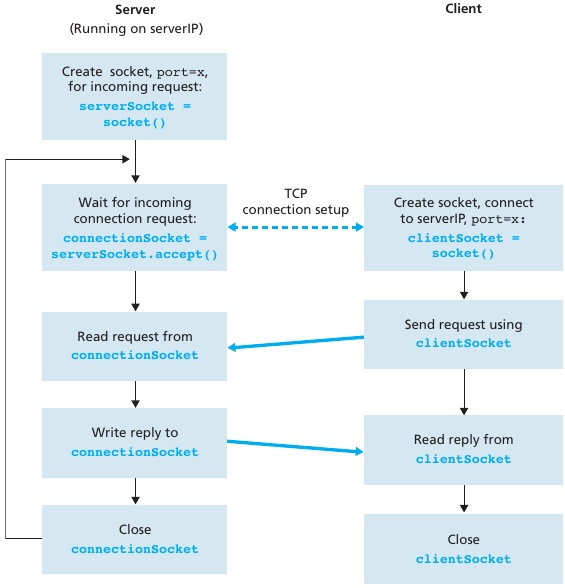
TCP socket identified by 4-tuple:
demux: receiver uses all four values to direct
segment to appropriate socket.
Server host may support many simultaneous TCP sockets:
Each socket is identified by its own 4-tuple.
Web servers have different sockets for each connecting client.
Non-persistent HTTP will have different socket for each request.
UDP looked like this:
TCP looks like this (e.g., Web server and two clients):
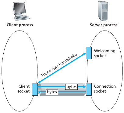
Connection-orientation:
Transmission Control Protocol is a connection-oriented protocol.
This means that it requires handshaking to set up end-to-end
communications.
Once a TCP connection is made via a 3-way handshake, an application
sends data simply by writing to that connection.
No further application-level addressing is needed.
TCP connections are managed by the operating-system kernel, not by the
application.
As part of TCP connection establishment, both sides of the connection
will initialize many TCP state variables in memory.
Reliable:
Manages message acknowledgment, re-transmission, and timeout.
Multiple attempts to deliver the message are made.
If part of a message gets lost along the way, the server will re-request
the lost part.
There will be either no missing data, or, in case of multiple timeouts,
a connection is dropped.
TCP numbers each packet, keeps track of which are lost, and re-transmits
them after a timeout.
It holds early-arriving out-of-order packets for delivery in the correct
sequence at a later time.
Every arriving data packet is acknowledged by the receiver.
Timeout and re-transmission occurs when an acknowledgment packet isn’t
received by the sender within a given time.
Ordered data transfer:
If two messages are sent over a connection in sequence, the first
message will reach the receiving application first.
When data segments arrive in the wrong order, TCP buffers delay the
out-of-order data until all data can be properly re-ordered and
delivered to the application.
The destination host re-arranges received packets according to sequence
number
Heavyweight:
TCP requires three packets to set up a socket connection, before any
user data can be sent.
TCP handles reliability and congestion control.
Streaming:
Data is read as a byte stream:
From the perspective of the application, no distinguishing indications
are transmitted to signal message (segment) boundaries.
An application using TCP can write 1 byte at a time, or 100 kB at a
time.
TCP will buffer and/or divide up the data into appropriate sized
packets.
Re-transmission of lost packets:
Any parts of the cumulative stream not acknowledged are
re-transmitted.
Error-free data transfer:
Service guarantees data were transmitted veritably.
Flow control:
Limits the rate that a sender transfers data, to facilitate consistent
delivery.
The receiver continually hints to the sender how much data can be
received.
Controlled by a sliding window parameter.
When the receiving host’s buffer fills, the next acknowledgment contains
a 0 in the window size, to stop transfer and allow the data in the
buffer to be processed.
Thus, sender will not overwhelm receiver’s buffers.
Congestion control:
Self-throttles to fairly utilize bandwidth between all connections.
Point-to-point:
Always between a single sender and a single receiver (not multiple).
Full duplex
Once a connection is set up, user data may be sent bi-directionally over
the connection.
If there is a TCP connection between Process A on one host and Process B
on another host, then application-layer data can flow from Process A to
Process B at the same time as application-layer data flows from Process
B to Process A.
TCP connection consists of both:
buffers, variables, and a socket connection to a process in one host,
and
another set of buffers, variables, and a socket connection to a process
in another host.
No buffers or variables are allocated to the connection in the network
elements (routers, switches, and repeaters) between the hosts.
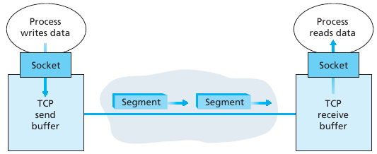
TCP directs data to the connection’s send buffer, which is one of the
buffers that is set aside during the initial three-way handshake.
From time to time, OS’s TCP core will grab chunks of data from the send
buffer and pass the data to the network layer.
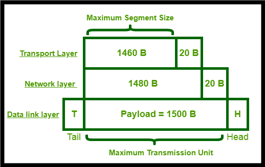
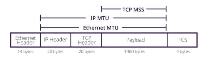
The maximum amount of data that can be grabbed and placed in a segment
is limited by the maximum segment size (MSS).
The MSS is typically set by first determining the length of the largest
link-layer frame that can be sent by the local sending host (the
so-called maximum transmission unit, MTU), and then setting the MSS to
ensure that a TCP segment (when encapsulated in an IP datagram) plus the
TCP/IP header length (typically 40 bytes) will fit into a single
link-layer frame.
TCP pairs each chunk of client data with a TCP header, thereby forming
TCP segments.
The segments are passed down to the network layer, where they are
separately encapsulated within network-layer IP datagrams.
The IP datagrams are then sent into the network.
When TCP receives a segment at the other end, the segment’s data is
placed in the TCP connection’s receive buffer.
+++++++++++++++++++++++ Cahoot-03-3
What identifies a TCP stream?
Sequence number (32 bits), acknowledgment number (32 bits),
and window (16 bits)
Used to provide a reliable data transfer, using a window-based
protocol.
In a TCP bytestream, each byte of the stream consumes one sequence
number.
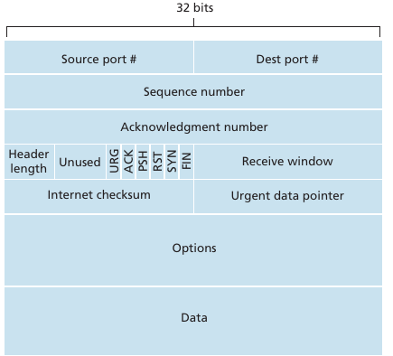
Segment structure details (also observe this is Wireshark, and
compare side-by-side):
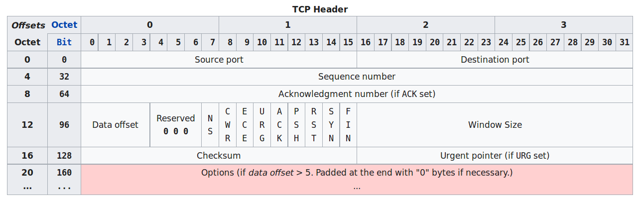
Source port (16 bits)
Identifies the sending port.
Destination port (16 bits)
Identifies the receiving port.
Sequence number (32 bits)
For reliability.
Has a dual role:
If the SYN flag is set (1), then this is the initial sequence
number.
The sequence number of the actual first data byte and the acknowledged
number in the corresponding ACK are then this sequence number plus
1.
If the SYN flag is clear (0), then this is the accumulated sequence
number of the first data byte of this segment for the current
session.
Acknowledgment number (32 bits)
For reliability.
If the ACK flag is set then the value of this field is the next sequence
number that the sender of the ACK is expecting.
This acknowledges receipt of all prior bytes (if any).
The first ACK sent by each end acknowledges the other end’s initial
sequence number itself, but no data.
Data offset (4 bits)
Specifies the size of the TCP header in 32-bit words.
The minimum size header is 5 words and the maximum is 15 words thus
giving the minimum size of 20 bytes and maximum of 60 bytes, allowing
for up to 40 bytes of options in the header.
This field gets its name from the fact that it is also the offset from
the start of the TCP segment to the actual data.
Reserved (3 bits)
For future use and should be set to zero.
Flags (9 bits) (aka Control bits)
Window size (16 bits)
For flow control.
The size of the receive window, which specifies the number of window
size units (by default, bytes) (beyond the segment identified by the
sequence number in the acknowledgment field) that the sender of this
segment is currently willing to receive (see Flow control and Window
Scaling).
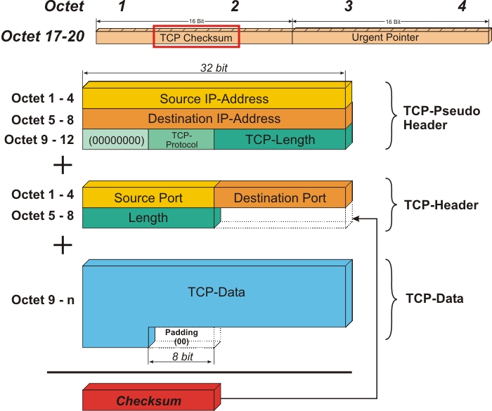
Checksum (16 bits)
The 16-bit checksum field is used for error-checking of the header, the
Payload, and a Pseudo-Header.
The Pseudo-Header consists of the Source IP Address, the Destination IP
Address, the protocol number for the TCP-Protocol (0x0006), and the
length of the TCP-Headers including Payload (in Bytes).
Urgent pointer (16 bits)
If the URG flag is set, then this 16-bit field is an offset from the
sequence number indicating the last urgent data byte.
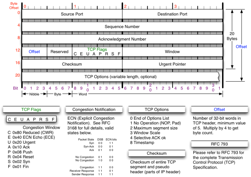
Options (Variable 0320 bits, divisible by 32)
* The length of this field is determined by the data offset field.
Options have up to three fields: Option-Kind (1 byte), Option-Length (1
byte), Option-Data (variable). The Option-Kind field indicates the type
of option, and is the only field that is not optional. Depending on what
kind of option we are dealing with, the next two fields may be set: the
Option-Length field indicates the total length of the option, and the
Option-Data field contains the value of the option, if applicable. For
example, an Option-Kind byte of 0x01 indicates that this is a No-Op
option used only for padding, and does not have an Option-Length or
Option-Data byte following it. An Option-Kind byte of 0 is the End Of
Options option, and is also only one byte. An Option-Kind byte of 0x02
indicates that this is the Maximum Segment Size option, and will be
followed by a byte specifying the length of the MSS field (should be
0x04). This length is the total length of the given options field,
including Option-Kind and Option-Length bytes. So while the MSS value is
typically expressed in two bytes, the length of the field will be 4
bytes (+2 bytes of kind and length). In short, an MSS option field with
a value of 0x05B4 will show up as (0x02 0x04 0x05B4) in the TCP options
section. Some options may only be sent when SYN is set; they are
indicated below as [SYN]. Option-Kind and standard lengths given as
(Option-Kind,Option-Length).
* 0 (8 bits): End of options list
* 1 (8 bits): No operation (NOP, Padding) This may be used to align
option fields on 32-bit boundaries for better performance.
* 2,4,SS (32 bits): Maximum segment size (see maximum segment size)
[SYN]
* 3,3,S (24 bits): Window scale (see window scaling for details)
[SYN][10]
* 4,2 (16 bits): Selective Acknowledgment permitted. [SYN] (See
selective acknowledgments for details)[11]
* 5,N,BBBB,EEEE,… (variable bits, N is either 10, 18, 26, or 34)-
Selective Acknowledgment (SACK)[12] These first two bytes are followed
by a list of 14 blocks being selectively acknowledged, specified as
32-bit begin/end pointers.
* 8,10,TTTT,EEEE (80 bits)- Timestamp and echo of previous timestamp
(see TCP timestamps for details)
* The remaining options are historical, obsolete, experimental, not yet
standardized, or unassigned. Option number assignments are maintained by
the IANA.
Padding
The TCP header padding is used to ensure that the TCP header ends, and
data begins, on a 32 bit boundary. The padding is composed of zeros.
The robustness principle (good advice in networking and in life…):
The handling of the TCP options by TCP implementations is one of the many applications of the robustness principle, which is usually attributed to Jon Postel, and is often quoted as:
“Be liberal in what you accept, and conservative in what you send” RFC 1122
In other words:
Even when you have the capacity to understand complexity and variety,
speak simply.
Can you accurately explain a complex topic to someone who does not have
a full mastery your native language?
The robustness principle implies that a TCP implementation should be
able to accept TCP options that it does not understand, and that it
should be able to parse any received segment without crashing, even if
the segment contains an unknown TCP option.
These options come in initially received SYN segments.
Options that have not been proposed by the client in the SYN segment, a
server should not send in the SYN+ACK segment or later segments.
TCP checksum also has extra IP information added:
Minor layering mix-up.
TCP and IP were not independent layers long ago (TCP/IP).
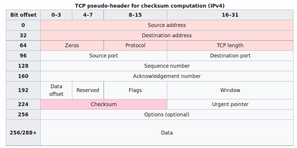
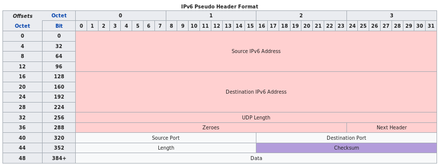
The method used to compute the checksum is changed, as per RFC
2460:
Any transport or other upper-layer protocol that includes the addresses
from the IP header in its checksum computation must be modified for use
over IPv6, to include the 128-bit IPv6 addresses instead of 32-bit IPv4
addresses.
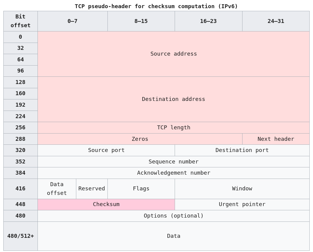
Source address:
The one in the IPv6 header.
Destination address:
The final destination.
If the IPv6 packet doesn’t contain a Routing header, TCP uses the
destination address in the IPv6 header.
Otherwise, at the originating node, it uses the address in the last
element of the Routing header, and, at the receiving node, it uses the
destination address in the IPv6 header.
TCP length:
The length of the TCP header and data.
Next Header:
The protocol value for TCP (6).
More to come below (protocol operation).
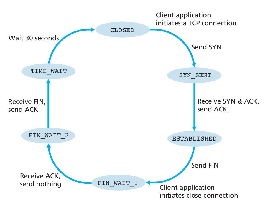
TCP protocol operations may be divided into three phases.
1. Connections must be properly established in a multi-step handshake
process (connection establishment)
2. before entering the data transfer phase.
3. After data transmission is completed, the connection termination
closes established virtual circuits and releases all allocated
resources.
Trace visiting:
*_socket_TCP*.py in wiresharkFollow protocol, lest your rock climbing partner falls to their
death…
Climber: “On belay?” (Are you ready to belay me?)
Belayer: “Belay on.” (Slack is gone and I’m ready.)
Climber: “Climbing.” (I’m going to climb now.)
Belayer: “Climb on.” (I’m ready for you to climb.)
Show below in Wireshark, with relative and real sequence numbers; compare side-by-side.
First, if the server is NOT accepting
connections:
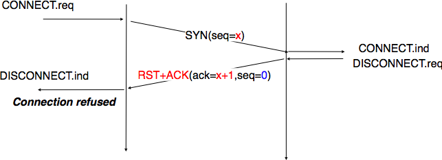
Will be relevant later (nmap uses this).
Second, if the server IS accepting
connections:
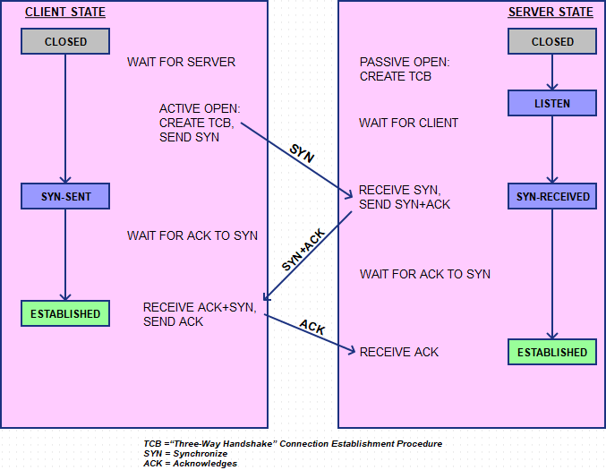
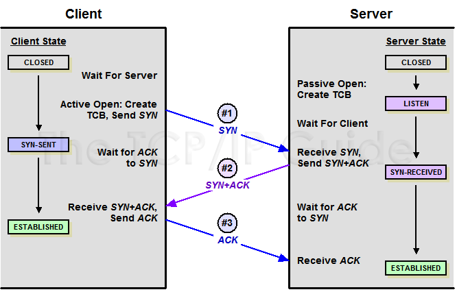
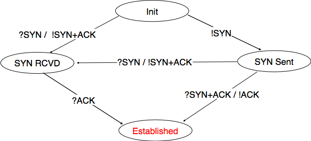
To establish a connection, TCP uses a three-way handshake.
Before a client attempts to connect with a server, the server must first
bind to and listen at a port to open it up for connections: this is
called a passive open.
Once the passive open is established, a client may initiate an active
open.
To establish a connection, the three-way (or 3-step) handshake
occurs:
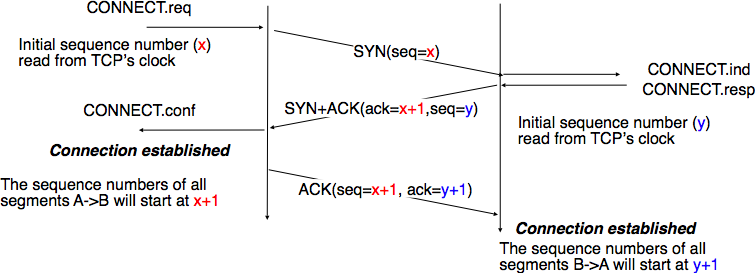
At this point, both the client and server have received an
acknowledgment of the connection.
The steps 1, 2 establish the connection parameter (sequence number) for
one direction and it is acknowledged.
The steps 2, 3 establish the connection parameter (sequence number) for
the other direction and it is acknowledged.
With these, a full-duplex communication is established.
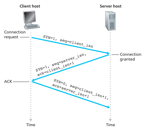
Step 1. syn
Step 2. synack
The connection-granted segment is referred to as a SYNACK segment.
Step 3. ack
Once these three steps have been completed, the client and server hosts can send segments containing data to each other.
In each of these future segments, the SYN bit will be set to zero.
Note that in order to establish the connection, three packets are sent between the two hosts
In full detail:
Simultaneous establishment of a TCP connection (rare, weird)
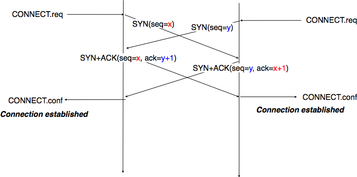
Show this in Wireshark, with relative and real sequence numbers; compare side-by-side.
When a connection ends, the “resources” (that is, the buffers and variables) in the hosts are de-allocated.


A’s FIN is, in effect, a promise to B not to send any more.
However, A must still be prepared to receive data from B, hence the
optional data shown in the diagram.
A good example of this occurs when A is sending a stream of data to B to
be sorted.
A sends FIN to indicate that it is done sending, and only then does B
sort the data and begin sending it back to A. This can be generated with
the command, on A:
$cat thefile | ssh B sort.
That said, the presence of the optional B-to-A data above following A’s
FIN is relatively less common.
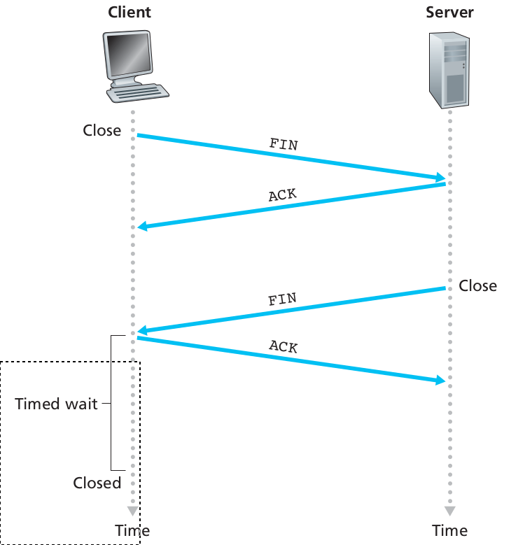
In the diagram above, A sends a FIN to B and receives an ACK, and then,
later, B sends a FIN to A and receives an ACK.
This essentially amounts to two separate two-way closure handshakes.
In the absence of the optional data from B to A after A sends its
FIN, the closing sequence reduces to the left-hand diagram below:

Relative:
| Num | A sends | B sends |
|---|---|---|
| 1 | SYN, seq=0 | |
| 2 | SYN+ACK, seq=0, ack=1 (expecting) | |
| 3 | ACK, seq=1, ack=1 (ACK of SYN) | |
| 4 | “abc”, seq=1, ack=1 | |
| 5 | ACK, seq=1, ack=4 | |
| 6 | “defg”, seq=4, ack=1 | |
| 7 | seq=1, ack=8 | |
| 8 | “foobar”, seq=8, ack=1 | |
| 9 | seq=1, ack=14, “hello” | |
| 10 | seq=14, ack=6, “goodbye” | |
| 11,12 | seq=21, ack=6, FIN | seq=6, ack=21 ;; ACK of “goodbye”, crossing packets |
| 13 | seq=6, ack=22 ;; ACK of FIN | |
| 14 | seq=6, ack=22, FIN | |
| 15 | seq=22, ack=7 ;; ACK of FIN |

Recall: these sequence numbers are actually big
numbers, that differ relatively by the amounts above (and as displayed
in Wireshark).
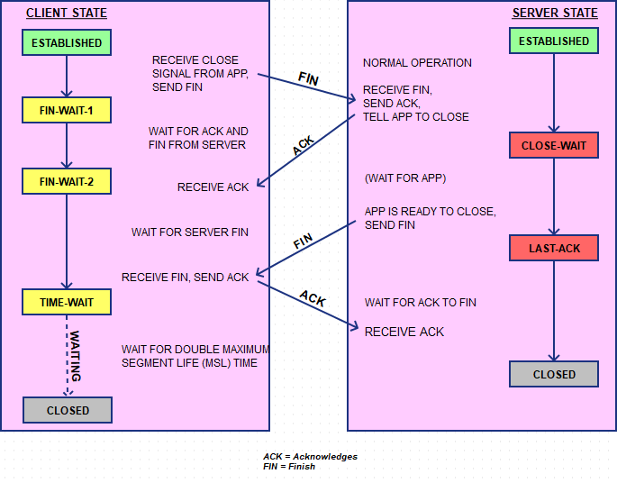
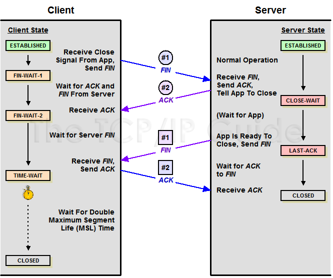
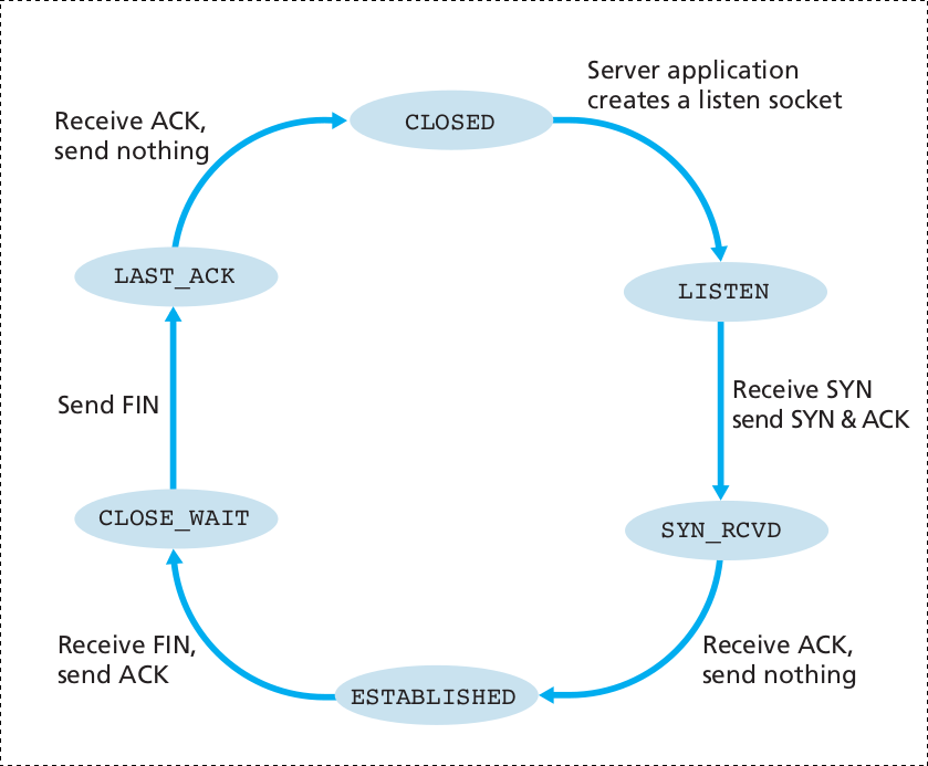
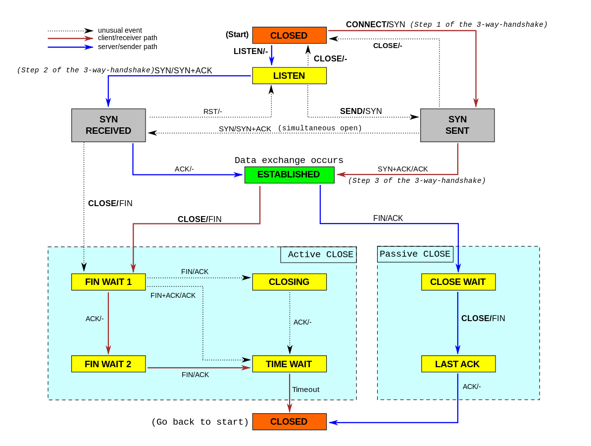
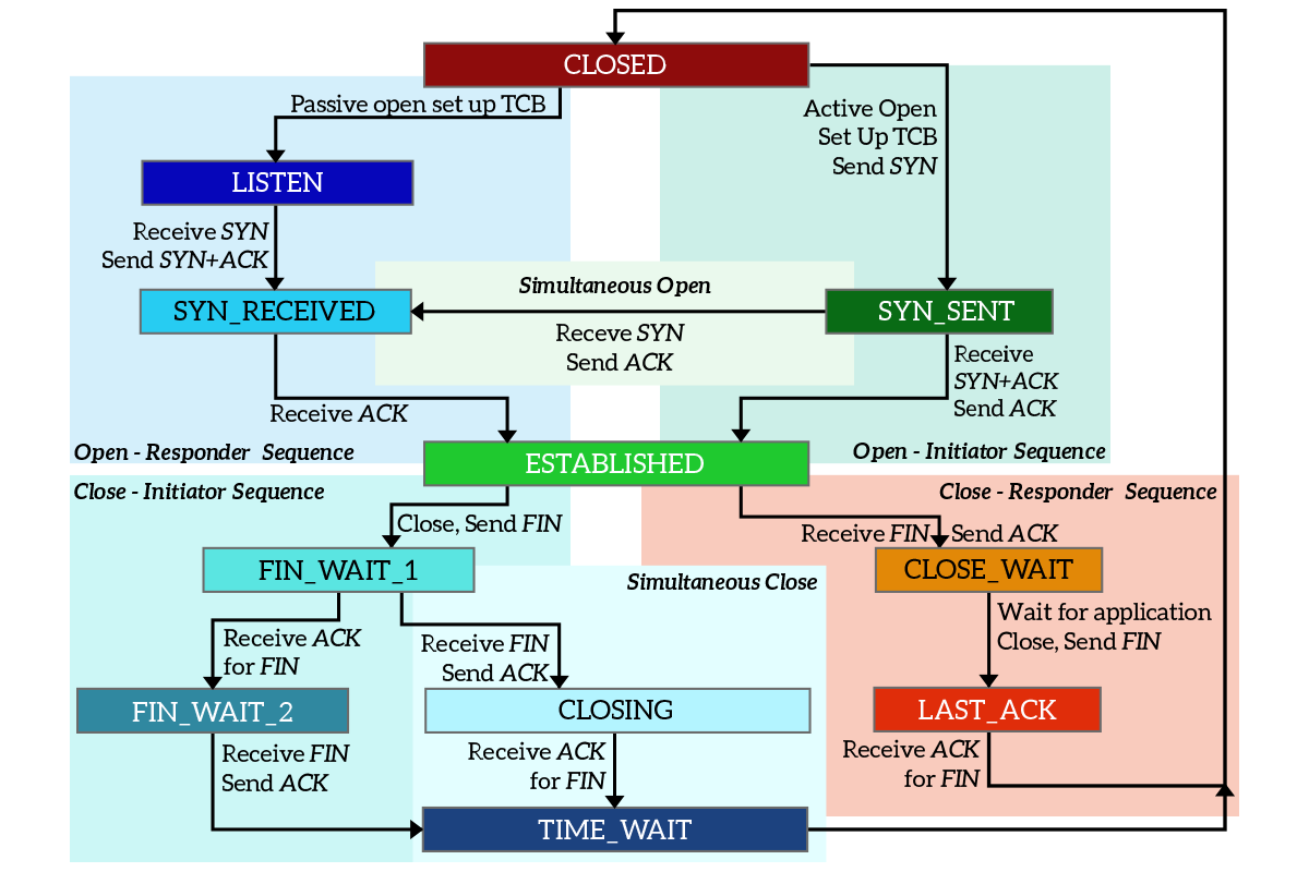
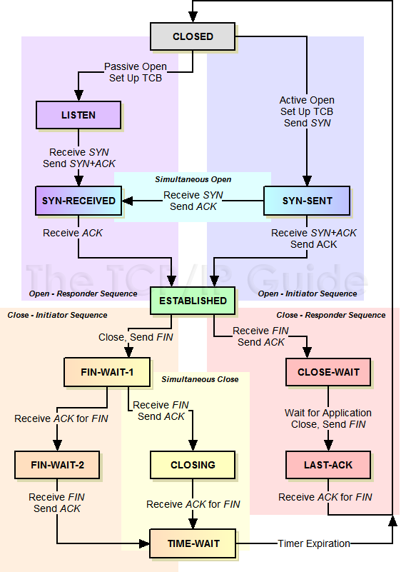
During the lifetime of a TCP connection, the local end-point undergoes a series of state changes:
++++++++++++++++++++ Cahoot-03-4
Trace Wireshark
Download this:
http://gaia.cs.umass.edu/wireshark-labs/alice.txt
Upload this:
http://gaia.cs.umass.edu/wireshark-labs/TCP-wireshark-file1.html
Starting from the Established state, there are two main paths through the below FSM.
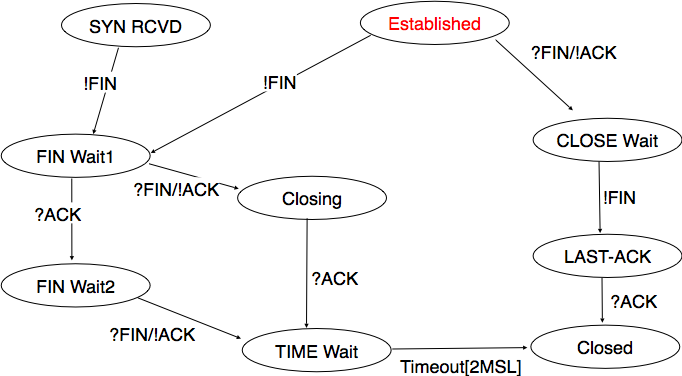
Both establishment and termination:
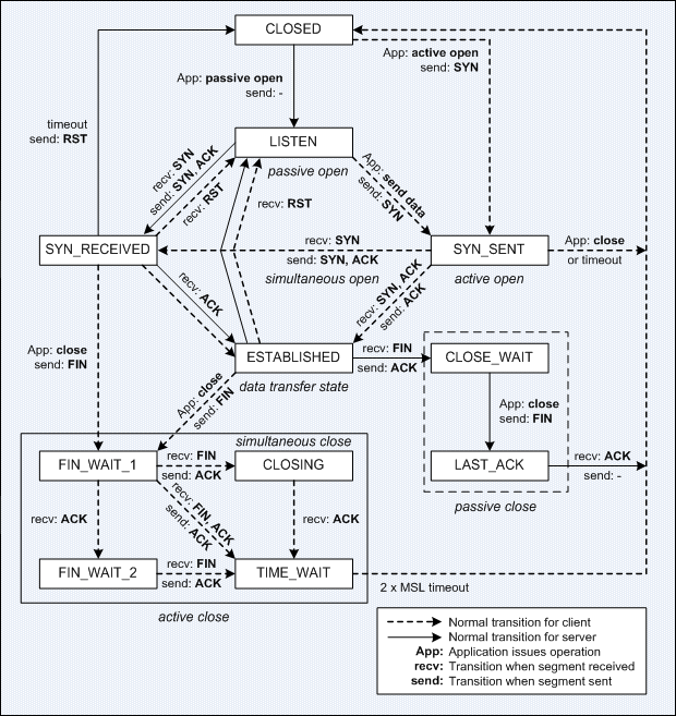
For more detail, see:
http://www.medianet.kent.edu/techreports/TR2005-07-22-tcp-EFSM.pdf
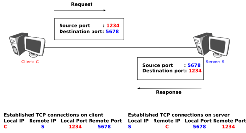
This is what is kept associated with the “table” of all current streams, in RAM, for both the client and the server:
Most implementations allocate an entry in a table that maps a session
to a running operating system process.
Because TCP packets do not include a session identifier, both endpoints
identify the session using the client’s address and port.
Whenever a packet is received, the TCP implementation must perform a
lookup on this table to find the destination process.
Each entry in the table is known as a Transmission Control
Block or TCB.
It contains information about the endpoints (IP and port), status of the
connection, running data about the packets that are being exchanged and
buffers for sending and receiving data.
The number of sessions in the server side is limited only by memory and
can grow as new connections arrive, but the client must allocate a
random port before sending the first SYN to the server.
This port remains allocated during the whole conversation, and
effectively limits the number of outgoing connections from each of the
client’s IP addresses.
If an application fails to properly close non-required connections, a
client can run out of resources and become unable to establish new TCP
connections, even from other applications.
Both endpoints must also allocate space for unacknowledged packets and
received (but unread) data.
+++++++++++++++++++++ Cahoot-03-5
https://en.wikipedia.org/wiki/Port_scanner
https://en.wikipedia.org/wiki/Nmap
Our discussion above has assumed that both the client and server are
prepared to communicate,
i.e., that the server is listening on the port to which the client sends
its SYN segment.
What if a host receives a mis-matched TCP segment,
whose port numbers or source IP address do not match any existing
sockets in the host?
For example, suppose a host receives a TCP SYN packet with destination
port 80,
but the host is not accepting connections on port 80
(that is, it is not running a Web server on port 80).
Then the host will send a special reset segment to the source.
This TCP segment has the RST flag bit set to 1.
Thus, when a host sends a reset segment, it is telling the source:
“I don’t have a socket for that segment. Please do not resend the
segment.”
When a host receives a UDP packet whose destination port number doesn’t
match with an ongoing UDP socket,
the host often sends a special ICMP datagram.
Now that we have a good understanding of TCP connection
management,
let’s revisit the nmap port-scanning tool and examine more closely how
it works.
To explore a specific TCP port, say port 6789, on a target
host,
nmap will send a TCP SYN segment with destination port 6789 to that
host.
There are three possible outcomes:
The source host receives a TCP SYNACK segment from the target host. Since this means that an application is running with TCP port 6789 on the target post, nmap returns “open.”
The source host receives a TCP RST segment from the target host. This means that the SYN segment reached the target host, but the target host is not running an appli- cation with TCP port 6789. But the attacker at least knows that the segments destined to the host at port 6789 are not blocked by any firewall on the path between source and target hosts. (Firewalls are discussed in Chapter 8.)
The source receives nothing. This likely means that the SYN segment was blocked by an intervening firewall and never reached the target host.
Nmap is a powerful tool, which can “case the joint” not only for open
TCP ports, but also for open UDP ports, for firewalls and their
configurations, and even for the versions of applications and operating
systems.
Much of this is done by manipulating TCP connection-management or other
administrative segments, for example:
syn scan, ack scan, fin scan, window scan
Recall:
Green box above in TCP’s FSM.
For actual data-containing packets, a complex set of protocol details exist.
The first designs did not have all the features we’re covering,
which were slowly added over time:
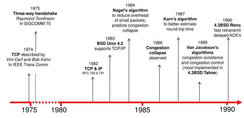
Now, there are many variations on TCP:
https://en.wikipedia.org/wiki/TCP_congestion_control#Algorithms
Maximizing transfer - sending many packets
optimistically and rapidly
Reliability and ordered transfer - whole packet
loss
Error detection - corrupt packets
Flow control - don’t overwhelm the receiver
Congestion control - dealing with queues and full
pipes
Stop and wait versus pipe-lining
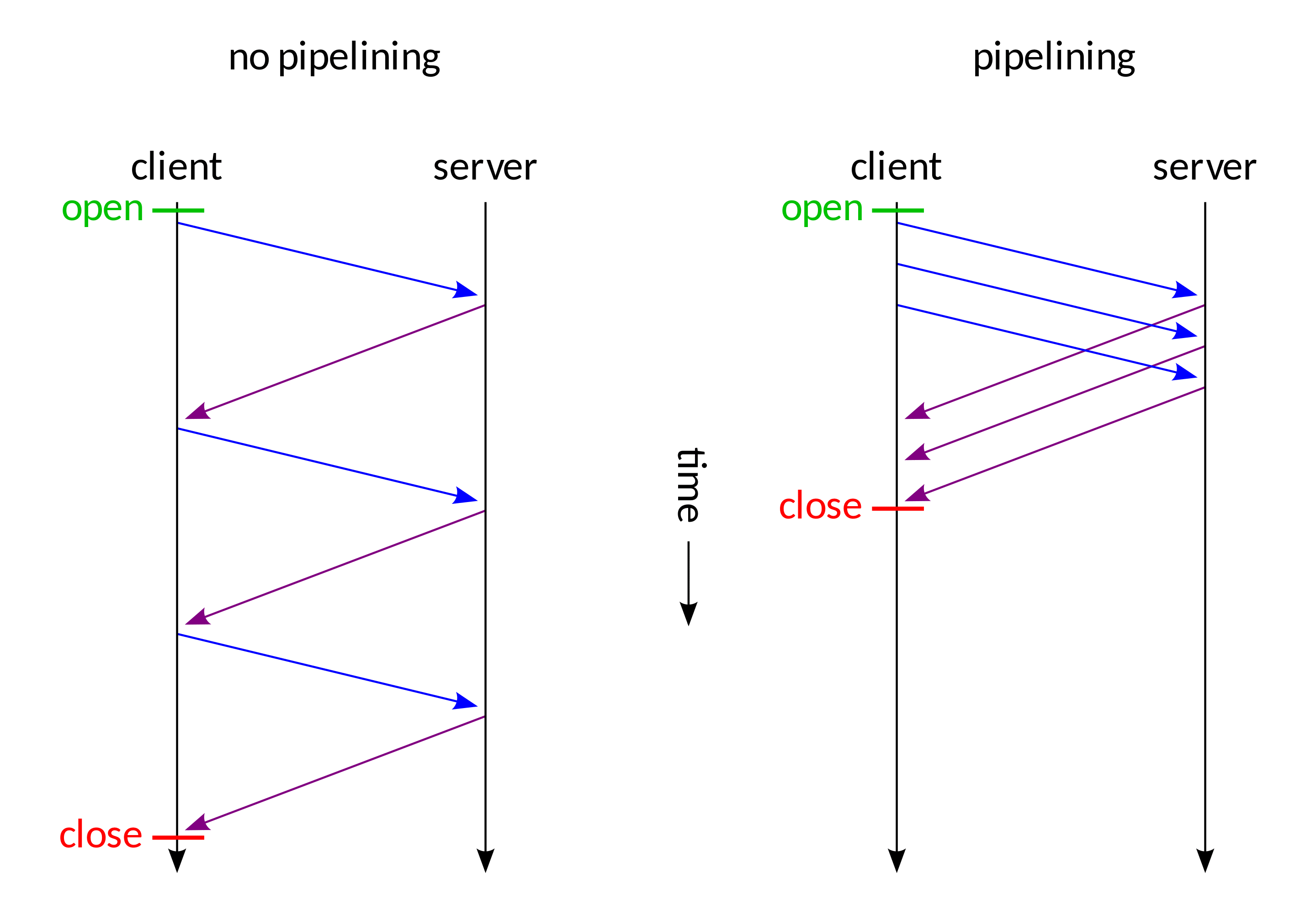
Pipelining requires that we think about pipelined acknowledgments and
pipelined reliability.
Receive window:
Computer-Networking
https://www.computer-networking.info/1st/html/transport/principles.html
https://www.computer-networking.info/2nd/html/principles/reliability.html
IntroNetworks
http://intronetworks.cs.luc.edu/current2/uhtml/slidingwindows.html
Reliability defines protocols for whole packet loss.
Reliability is not defined as dealing with corrupted packets,
which is handled by error detection below.
Two mechanisms for detecting lost packets:
1. Duplicate acknowledgment based re-transmission (dup-ack)
2. Timeout based re-transmission
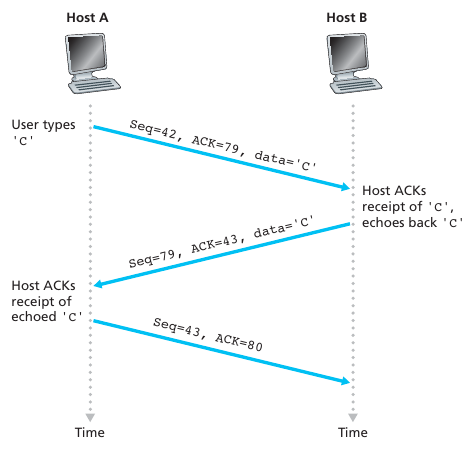
Reminder: Sequence and acknowledgment numbers
Recall:
TCP Acknowledgments are cumulative and
positive.
We only acknowledge the last received packet,
of a continuous cumulative chain of packets from the
start.
Make sure you get this point before continuing!
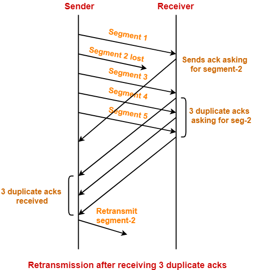
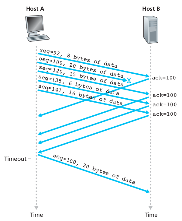
Duplicate acknowledgment based re-transmission
(dup-ack):
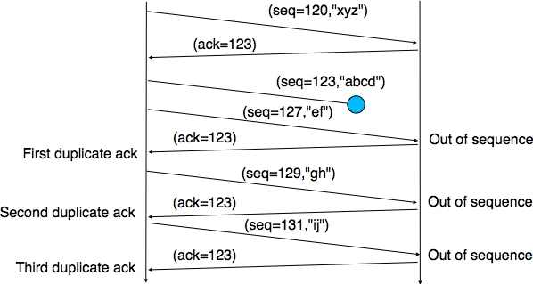
If a single packet (say packet 127) in a stream is lost,
then the receiver cannot acknowledge packets above 127 because it uses
cumulative ACKs.
Hence the receiver acknowledges packet 123 again on the receipt of
another data packet.
This duplicate acknowledgment is used as a signal for packet loss.
That is, if the sender receives three duplicate acknowledgments,
it re-transmits the last un-acknowledged packet.
A threshold of three is used,
because the network may reorder packets causing duplicate
acknowledgments.
This threshold avoids spurious re-transmissions due to reordering,
though it is still possible.
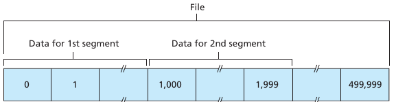
Indirectly “asking for segment-2”,
is actually just an ack of segment-1:
Question:
When pipelining, if we just lose one packet,
do we have to re-transmit everything,
or just the lost packet?
Sometimes, selective acknowledgments (SACKs) are used,
providing more explicit feedback on which packets have been
received.
This improves TCP’s ability to re-transmit the right packets.
++++++++++++++++++++++++++ Cahoot-03-6
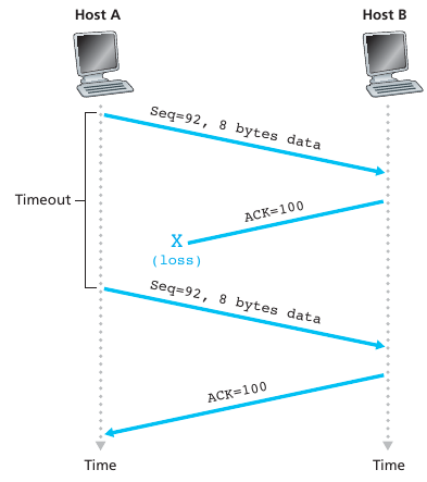
Timeout based re-transmission
Re-transmission due to a lost acknowledgment:
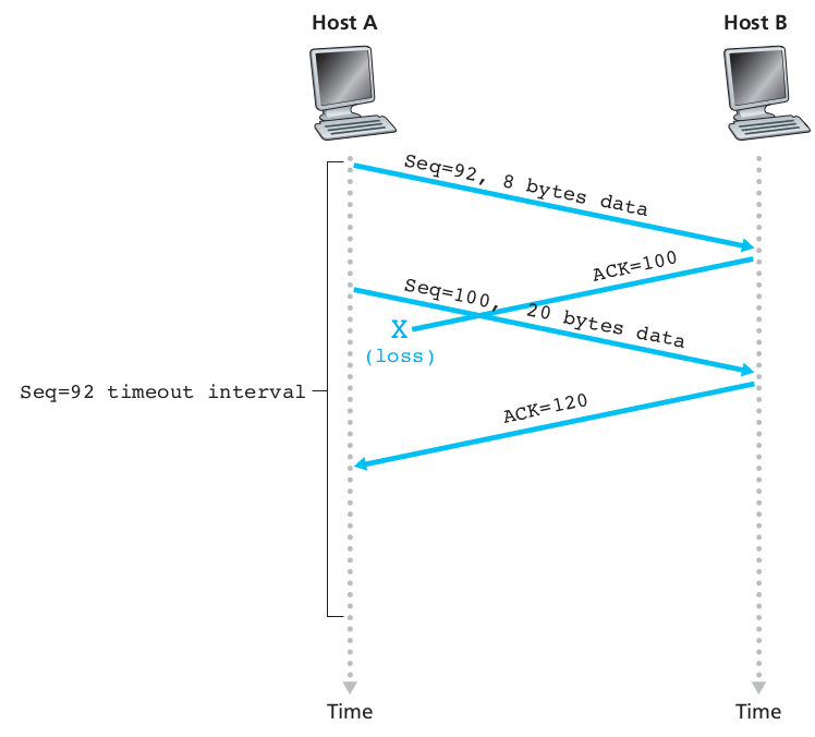
Cumulative acknowledgment avoids re-transmitting the lost
segment:
Aside/discuss:
What is the definition of control in CS/engineering?
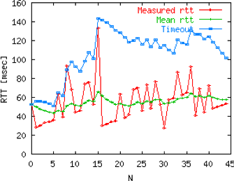
Round Trip Time (RTT) and timeout duration:
First, to decide when a packet has probably been lost,
one needs to know a reasonable timeout threshold.
How do we compute a round-trip time (RTT)?
One good was is an exponential weighted moving average (EWMA).
Whenever a packet is sent, the sender sets a timer.
The timer is set to a conservative prediction of when that packet will
be ack’ed.
If the sender does not receive an ACK by then,
then it transmits that packet again.
The timer is reset every time the sender receives an
acknowledgment.
This means that the re-transmit timer expires only when the sender has
received no acknowledgment for a long time.
Further, in the case a re-transmit timer has expired and no
acknowledgment is received,
the next timer is set to twice the previous value (up to a certain
threshold).
This helps defend against a man-in-the-middle denial of service
attack,
that tries to fool the sender into making so many re-transmissions that
the receiver is overwhelmed.
Summary:
If the sender infers that data has been lost in the network,
using one of the two techniques described above,
then it re-transmits the data.
Such real-time changing of parameters based on the environment creates
momentum,
feedback, and a dynamical distributed process,
especially when interacting with other TCP connections.
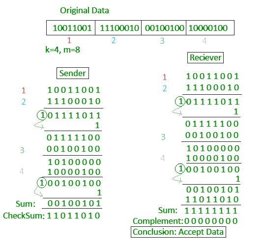
When reviewing the TCP header,
we talked about computing a checksum:
Fold bit-string into 16-bit page, sum bits, invert:
See checksum above, for packet corruption, not loss.
The TCP checksum is a weak check by modern standards
(statistically OK at detecting errors).
Data Link Layers with high bit error rates may require additional link
error correction/detection capabilities.
The weak checksum is partially compensated for by the common use of a
CRC or better integrity check at layer 2,
below both TCP and IP, such as is used in PPP or the Ethernet
frame.
However, this does not mean that the 16-bit TCP checksum is
redundant:
Remarkably, introduction of errors in packets between CRC-protected hops
is common,
but the end-to-end 16-bit TCP checksum catches most of these simple
errors.
This is the end-to-end principle at work.
A concrete example:
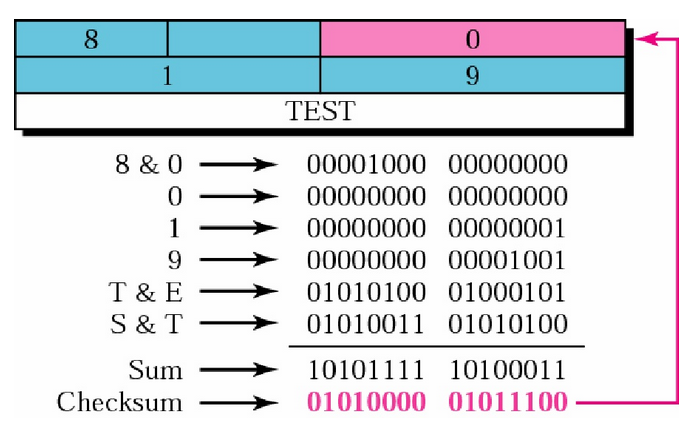
Receiver must do the same thing as sender, re-compute,
and compare the value to the checksum the sender sent:
+++++++++++++++++++++ Cahoot-03-7
Broad principles:
https://en.wikipedia.org/wiki/Flow_control_(data)
As a consequence of pipelining,
we must consider the rate at which we send data,
for our receiver’s ability to process it.
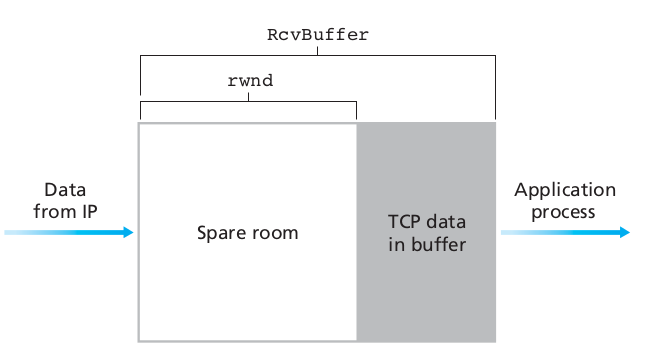
TCP provides flow control by having the sender maintain a variable
called the receive window.
Recall:
Receive window in header above,
receive buffer in TCP block.
The receive window provides the sender an idea of how much free
buffer space is available at the receiver.
Because TCP is full-duplex, the sender at each side of the connection
maintains a distinct receive window.
In each TCP segment, the receiver specifies in the receive
window field.
It defines the amount of additionally received data, in bytes,
that it is willing to buffer for the connection.
The sending host can send only up to that amount of data,
before it must wait for an acknowledgment and window update from the
receiving host.

TCP sequence numbers and receive windows behave very much like a
clock.
The receive window shifts each time the receiver receives and
acknowledges a new segment of data.
Once it runs out of sequence numbers, the sequence number loops back to
0.
The great thing about TCP jokes is that you always get
them.
The problem with TCP jokes is that I’ll keep retelling them slower until
you get them!
As a consequence of pipelining,
we must consider the rate at which we send data,
for our network’s ability to relay it.
A full topic on its own:
https://en.wikipedia.org/wiki/TCP_congestion_control
https://en.wikipedia.org/wiki/Additive_increase/multiplicative_decrease
V2
https://www.computer-networking.info/2nd/html/principles/sharing.html#network-congestion
https://www.computer-networking.info/2nd/html/principles/sharing.html#congestion-control
https://www.computer-networking.info/2nd/html/protocols/congestion.html
V1
https://www.computer-networking.info/1st/html/transport/tcp.html#tcp-congestion-control
Intronetworks
http://intronetworks.cs.luc.edu/current2/uhtml/intro.html#congestion
http://intronetworks.cs.luc.edu/current2/uhtml/reno.html
High level idea:
Q: How fast should sender send data, to not overwhelm the network?
A: ??
Q: How do we control the rate of sending data?
A: by controlling:
the number of packets out on the wire, un-acked,
and how rapidly we increase this number over time.
Reminder:
What is the definition of control in CS/engineering?
A quick preview (more detail to come):
cwnd is under fine-grained, step-wise contrtol.
ssthresh is a threshold that operates at a courser,
larger, intermittent timescale.
Q: How do we know we’ve overwhelmed the network?
A: by observing:
duplicate acks,
timeouts,
Explicit Congestion Notification (ECN) flag in TCP header (more
rare).
Q: Which indicates worse congestion?
A: A point to ponder, more below.
TCP block data:
cwnd
Fine control of sending rate, modulated to adjust speed.
A congestion window (cwnd) is maintained by the sender.
cwnd is one of the factors that determines the number
of bytes that can be outstanding at any time.
It thus determines the rate at which sender sends data.
This is not to be confused with the sliding window size which is
maintained by the receiver, for the purpose of determining how much data
the receiver’s buffers can handle.
Instead, reducing the congestion window is a means of reducing the
degree to which a link between the sender and the receiver is overloaded
with too much traffic.
It is reduced after observing evidence of congestion.
When a connection is set up, the congestion window, a value maintained
independently at each host, is set to a small multiple of the
MSS allowed on that connection.
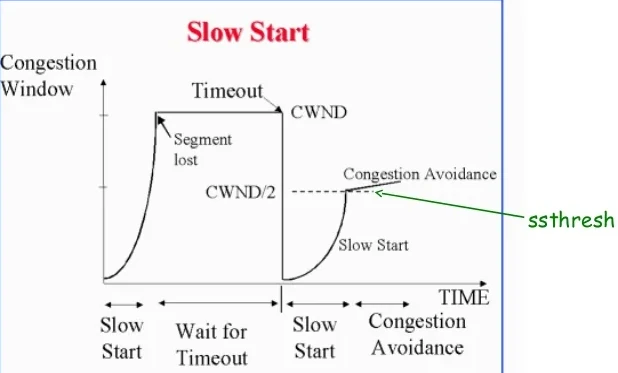
ssthresh
A value adjusted only intermittently
It is treated as an occasional set-point for modifying cwnd.
A slow-start threshold (ssthresh) determines how long a ramp-up in speed
occurs.
Both cwnd and ssthresh can be modulated over time, to control sending
rate.
cwnd is fine-grained control.
ssthresh is an occasional resetting threshold.
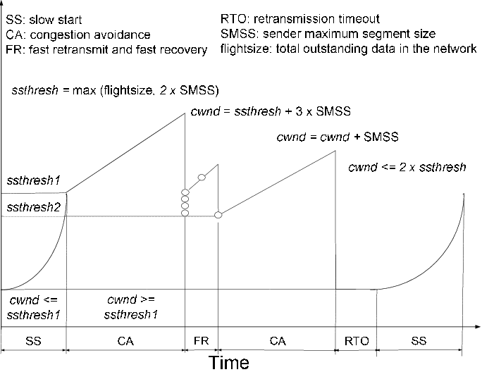
Most modern implementations of TCP contain four intertwined
parts:
1. slow-start
2. congestion avoidance
3. fast re-transmit (this is just 3xdup-ack)
4. fast recovery (in some versions only, varies)
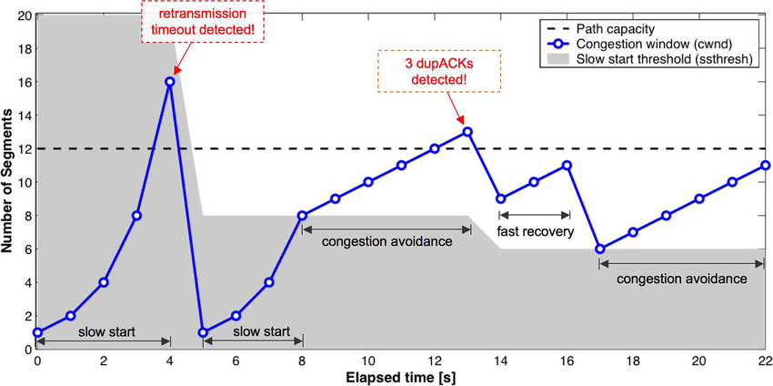
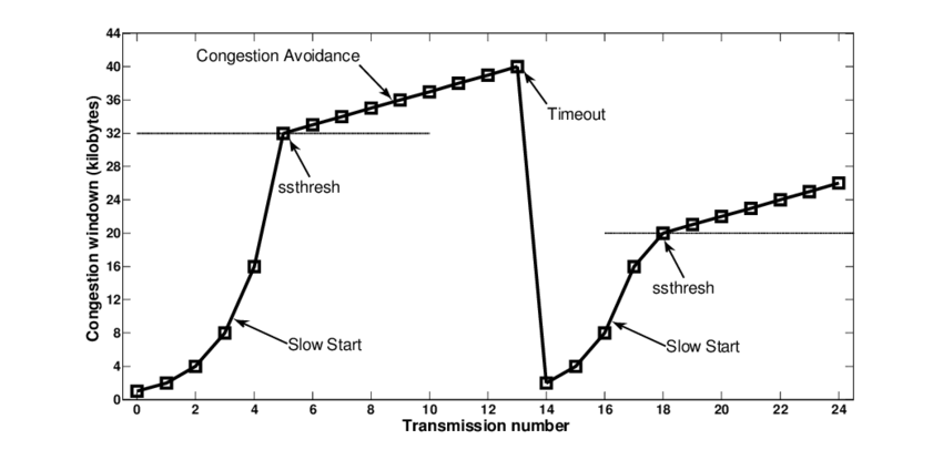
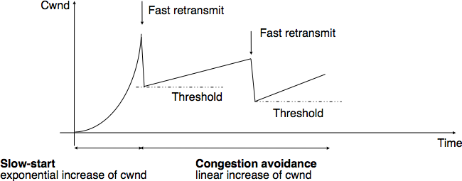
Overview:
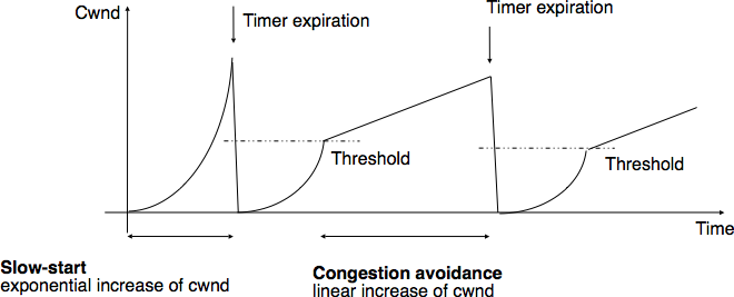
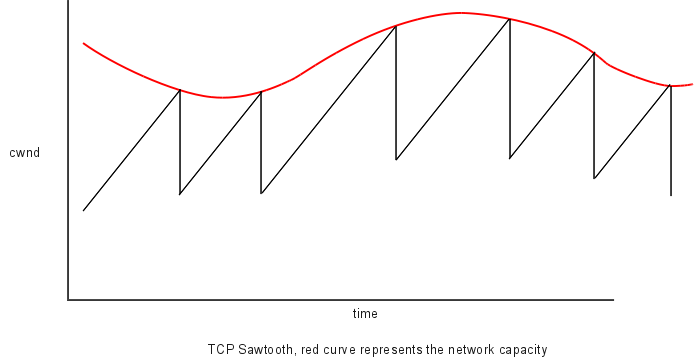
AIMD
Linear growth of cwnd, until a loss, then an exponential
reduction.
Additive increase, multiplicative decrease (AIMD).
Sawtooth is common behavior for a closed-loop control algorithm.
Types of congestion:
Mild congestion (dup-ack)
TCP considers that the network is lightly congested if it receives three
duplicate acknowledgements and performs a fast retransmit.
If the fast retransmit is successful, this implies that only one segment
has been lost.
In this case, TCP performs multiplicative decrease and the congestion
window is divided by 2.
The slow-start threshold is set to the new value of the congestion
window.
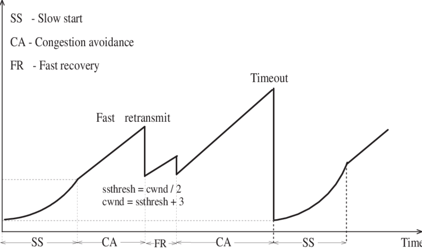
Severe congestion (timeout)
TCP considers that the network is severely congested when its
retransmission timer expires.
In this case, TCP retransmits the first segment, sets the slow-start
threshold to 50% of the congestion window.
The congestion window is reset to its initial value, and TCP performs a
slow-start.
Such behavior could be expressed in pseudocode:
# Initialisation
cwnd = MSS;
ssthresh = swin;

# Ack arrival
if tcp.ack > snd.una:  # new ack, no congestion
    if  cwnd < ssthresh :
        # slow-start: increase quickly cwnd
        # double cwnd  every rtt
        cwnd = cwnd + MSS
    else:
        # congestion avoidance : increase slowly cwnd
        # increase cwnd by one mss every rtt
        cwnd = cwnd + mss * (mss / cwnd)
else: # duplicate or old ack
    if tcp.ack==snd.una:    # duplicate acknowledgement
        dupacks++
        if dupacks==3:
            retransmitsegment(snd.una)
            ssthresh=max(cwnd / 2, 2 * MSS)
            cwnd=ssthresh
    else:
        dupacks=0
        # ack for old segment, ignored

Expiration of the retransmission timer:
    send(snd.una)     # retransmit first lost segment
    sshtresh=max(cwnd / 2, 2 * MSS)
    cwnd=MSS
This is a summary of many of the above mechanisms illustrated in FSM
form:
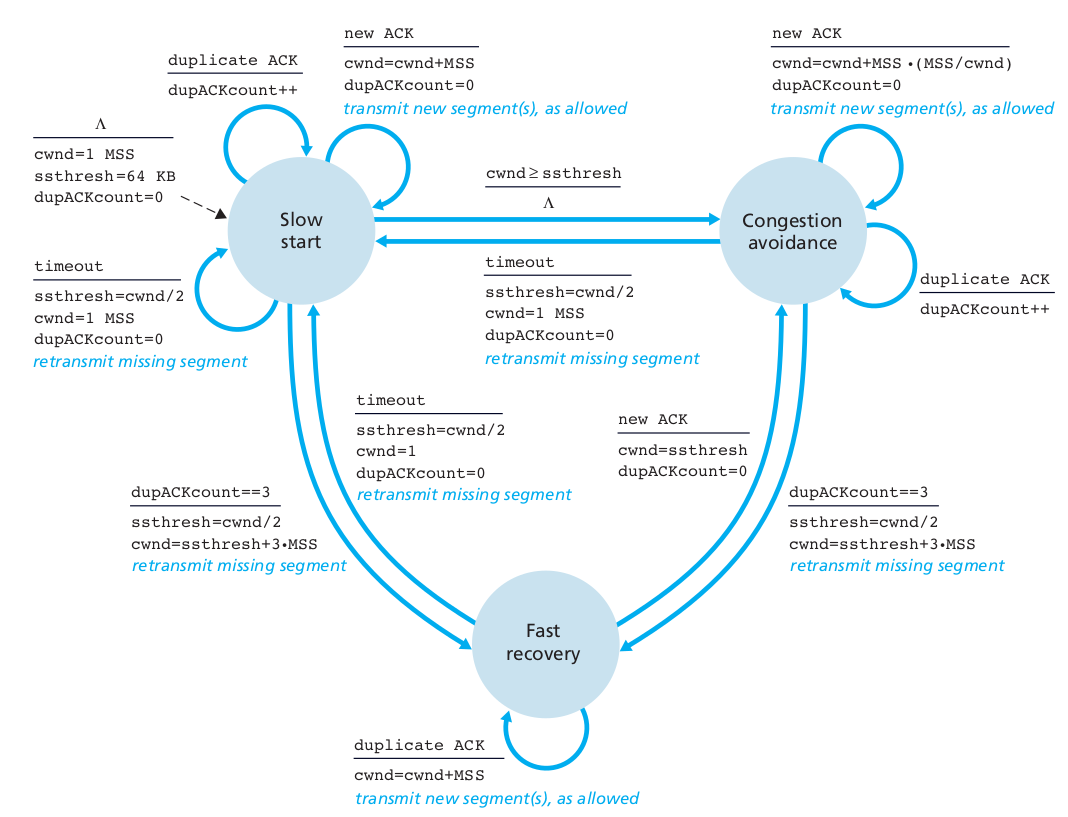
Note: pseudocode and FSM are not the same implementation.
+++++++++++++++++++++ Cahoot-03-8
This is an oddball field in TCP,
which is related to layers below (data-link).
The maximum segment size (MSS) is the largest amount of data, specified
in bytes, that a TCP entity is willing to receive in a single
segment.
Typically the MSS is announced by each side.
MSS announcement is also often called “MSS negotiation”, though that’s a
misnomer.
Two completely independent values of MSS are permitted for the two
directions of data flow in a TCP connection.
Why define a max size at the TCP layer?
IP constraints (one layer down from transport)
IP fragmentation (more later), can lead to packet loss and excessive
re-transmissions.
Thus, to optimize performance, each TCP entitiy’s MSS should be set
small enough.
When the TCP connection is established, MSS announcment uses the MSS
option field.
Why is there IP fragmentation?
Data-link constraints (two layers down from transport)
Each entity is connected to a data-link layer (the next one down).
There are many heterogeneous data-link networks between them.
Each data link layer defines a maximum transmission unit (MTU), above
which, it will not send.
Initialization
The initial MSS value is derived from the maximum transmission unit
(MTU) size of the data link layer network each TCP entitiy is attached
to.
After initialization
Dynamically adjust the MSS.
How?
TCP senders can use path MTU discovery to infer the minimum data-link
layer MTU along the network path between the sender and receiver.
This avoid IP fragmentation within the network.
Less fragmentation reduces loss.
Recall nmap?
Can you hide which ports are open?
Make a secret code to reveal them?
https://en.wikipedia.org/wiki/Port_knocking
Attacks:
UDP packets can easily be spoofed for amplification, redirection, or
flooding attacks.
It is easy to send UDP packets with spoofed source IP address.
The attacker sends a small message to a server, with spoofed source
address,
and the server then responds to the spoofed address with a much larger
response message.
This creates a larger volume of traffic to the victim,
than the attacker would be able to generate directly.
Defense:
One approach is for the server to limit the size of its response,
ideally to the size of the client’s request,
until it has been able to verify that the client actually receives the
packets,
sent to its claimed IP address; QUIC uses this approach.
https://en.wikipedia.org/wiki/Transmission_Control_Protocol#Vulnerabilities
http://seclab.cs.sunysb.edu/sekar/papers/netattacks.pdf
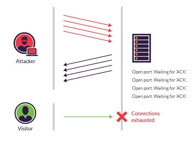
https://en.wikipedia.org/wiki/SYN_flood
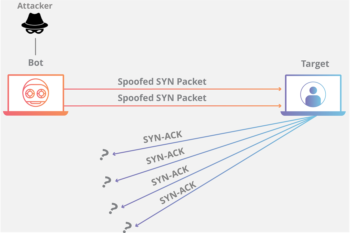
During three-way handshake,
in response to a received SYN,
the server allocates and initializes connection variables and
buffers.
The server then sends a SYNACK in response,
and awaits an ACK segment from the client.
If the client does not send an ACK,
to complete the third step of this 3-way handshake,
eventually, often after a minute or more,
the server will terminate the half-open connection,
and reclaim the allocated resources.
Attacker(s) send a large number of TCP SYN segments,
without completing the third handshake step.
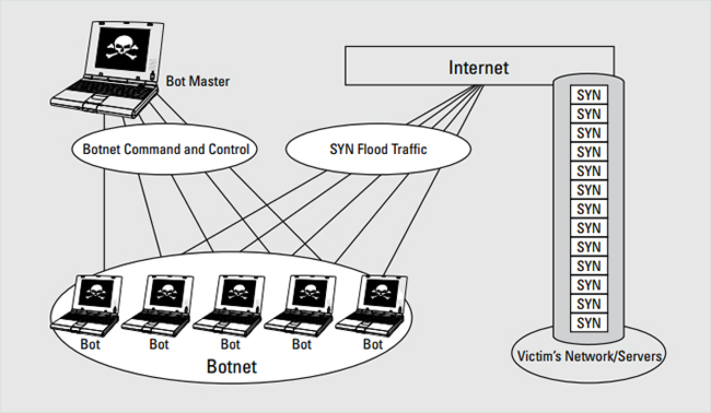
With this deluge of SYN segments,
the server’s connection resources become exhausted,
as they are allocated (but never used!) for half-open connections
Legitimate clients are then denied service.
PUSH and ACK floods are used in other variants of flood attacks.
Some servers attempt to detect syn-floods and fake connections.
https://en.wikipedia.org/wiki/Sockstress
Sockstress is an attack method similar to the floods above.
With a syn flood, the server may time out each attempted
connection.
To avoid this protective defense,
Sockstress provides more convincing evidence of real connection.
Sockstress is a user-land TCP socket stress framework,
that can complete arbitrary numbers of open sockets,
without incurring the typical overhead of tracking state.
Once the socket is established,
it is capable of sending TCP attacks,
that target specific types of kernel and system resources such as:
Counters, Timers, and Memory Pools.
Example, sub-variant:
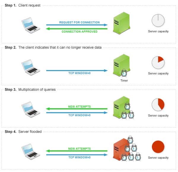
https://en.wikipedia.org/wiki/Sockstress#Zero_window_connection_stress
One way to convince the server each connection is real,
increasing timeouts, using a fake connect, and then send window of
0.
https://en.wikipedia.org/wiki/TCP_sequence_prediction_attack
Imagine an attacked who is on the same LAN, but is not the gateway
router.
Assuming the attacker does not control the full infrastructure (as an
ISP would),
and thus can not be a perfect MITM,
the attacker wants to send fake packets to a victim.
The attacker hopes to correctly guess the sequence number to be used by
the sending host.
If they can do this, they may be able to send counterfeit packets to the
receiving host.
These packets which will seem to originate from the real sending
host.
The attacker may issue packets using the same source IP address as a
host (spoofed).
By monitoring the traffic before an attack is mounted,
the malicious host can figure out the correct sequence number.
After the IP address and the correct sequence number are known,
it is a race between the attacker and the trusted host to get the
correct packet sent.
The attacker may DoS it’s victim.
Once the attacker has control over the connection,
they are able to send counterfeit packets without getting a
response.
If an attacker can cause delivery of counterfeit packets of this
sort,
they may be able to cause various sorts of mischief, including:
the injection into an existing TCP connection, of data of the attacker’s
choosing,
and the premature closure of an existing TCP connection,
by the injection of counterfeit packets with the RST bit set.
(TCP reset attack).
Note:
A TCP reset attack is easier if attacker is the ISP, why?
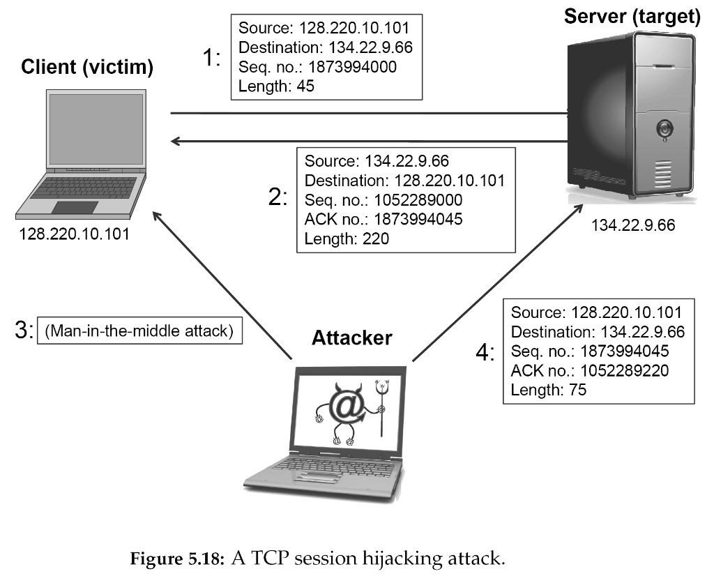
An attacker who is able to eavesdrop a TCP session,
and redirect packets, can hijack a TCP connection.
To do so, the attacker learns the sequence number from the ongoing
communication,
and forges a false segment that looks like the next segment in the
stream.
Such a simple hijack can result in one packet being erroneously accepted
at one end.
When the receiving host acknowledges the extra segment,
to the other side of the connection,
synchronization is lost.
Hijacking might be combined with Address Resolution Protocol (ARP)
spoofing,
or routing attacks that allow taking control of the packet flow,
so as to get permanent control of the hijacked TCP connection.
These are lower level, which we have not covered yet.
Partial fix:
Initial sequence number is now chosen at random.
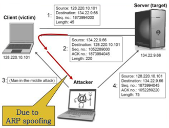
ARP spoofing (lower layer) we’ll cover latter,
as an extension to this attack.
An attacker who can eavesdrop,
and predict the size of the next packet to be sent,
can cause the receiver to accept a malicious payload,
without disrupting the existing connection.
The attacker injects a malicious packet with the sequence number,
and a payload size of the next expected packet.
When the legitimate packet is ultimately received,
it is found to have the same sequence number and length as a packet
already received,
and is silently dropped as a normal duplicate packet,
and the legitimate packet is “vetoed” by the malicious packet.
Unlike in connection hijacking,
the connection is never de-synchronized,
and communication continues as normal,
after the malicious payload is accepted.
TCP veto gives the attacker less control over the communication,
but makes the attack particularly resistant to detection.
https://ieeexplore.ieee.org/document/6497785
https://en.wikipedia.org/wiki/TCP_reset_attack
In most packets the reset RST bit is set to 0, and has no effect.
However, if the RST bit is set to 1,
then it indicates to the receiving computer that:
the computer should immediately stop using the TCP connection.
Thus, it should not send any more packets,
and discards any further packets it receives,
with headers indicating they belong to that connection.
A TCP reset kills a TCP connection instantly.
It is possible for a 3rd computer to monitor the TCP packets on the
connection,
and then send a “forged” packet containing a TCP reset to one or both
endpoints.
Who performs this attack?
Those with physical access to the wires/waves.
The Great Firewall of China and Iranian internet censorship mechanisms
are known to use TCP reset attack to interfere with and block
connections, as a method to carry out Internet censorship.
Comcast did this to people too:
In late 2007, Comcast began using forged TCP resets to cripple
peer-to-peer and certain groupware applications on their customers’
computers.
https://en.wikipedia.org/wiki/TCP_reset_attack#Comcast_Controversy
http://intronetworks.cs.luc.edu/current2/uhtml/tcpB.html#variants-and-alternatives
https://www.computer-networking.info/2nd/html/protocols/sctp.html
https://en.wikipedia.org/wiki/Transport_layer#Protocols
https://en.wikipedia.org/wiki/Micro_Transport_Protocol
(uTP)
http://bittorrent.org/beps/bep_0029.html
https://tools.ietf.org/html/rfc6817
Random examples of the hard way:
https://www.programcreek.com/python/example/7887/socket.SOCK_RAW
https://docs.python.org/3/library/struct.html
https://www.geeksforgeeks.org/struct-module-python/
Show these behave in wireshark:
Client
03-Transport/spoof_raw_UDP_client.py
Run the UDP server from the last lecture page before this.
A Packet sniffer for UDP (server)
03-Transport/spoof_raw_UDP_server.py
We can spoof port using this header.
Can we fake an a source IP address using just the TCP or UDP
transport layer header?
Do we have to fake any more headers?
Does the IP address go into the TCP header anywhere?
Do we have to fake any more headers to spoof a source IP address?
What is the difference between faking a DNS reply (as we did in
UDP),
and faking a source IP address?
++++++++++++ Cahoot-03-9
https://www.binarytides.com/raw-socket-programming-in-python-linux/
03-Transport/spoof_raw_TCP_socket.py
++++++++++++ Cahoot-03-10
https://www.binarytides.com/python-syn-flood-program-raw-sockets-linux/
03-Transport/spoof_syn_flood.py
In python (the easy way):
03-Transport/spoof_scapy.py
Scapy is really a nice library!
https://scapy.readthedocs.io/en/latest/
We’ll do an assignment with this upcoming.
Next: 04-NetworkData.html